- 您現(xiàn)在的位置:買賣IC網(wǎng) > PDF目錄382301 > MC33121 (Motorola, Inc.) LOW VOLTAGE SUBSCRIBER LOOP INTERFACE CIRCUIT PDF資料下載
參數(shù)資料
| 型號: | MC33121 |
| 廠商: | Motorola, Inc. |
| 英文描述: | LOW VOLTAGE SUBSCRIBER LOOP INTERFACE CIRCUIT |
| 中文描述: | 低電壓用戶環(huán)路接口電路 |
| 文件頁數(shù): | 14/32頁 |
| 文件大小: | 570K |
| 代理商: | MC33121 |
第1頁第2頁第3頁第4頁第5頁第6頁第7頁第8頁第9頁第10頁第11頁第12頁第13頁當(dāng)前第14頁第15頁第16頁第17頁第18頁第19頁第20頁第21頁第22頁第23頁第24頁第25頁第26頁第27頁第28頁第29頁第30頁第31頁第32頁

MC33121
14
MOTOROLA
Logic Interface (Hook status, pulse dialing, faults)
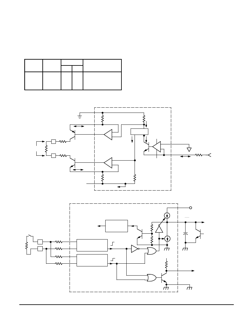
The logic interface section provides hookswitch status,
fault information, and pulse dialing information to the 4–wire
side of the system at the ST1 and ST2 outputs. Figure 30 is
a representative diagram.
The logic outputs operate according to the truth table in
Table 1:
Table 1. Status Output Truth Table
Hook
Status
Fault
Detection
Outputs
Circuit Condition
i C
di i
ST1
ST2
On–Hook
Off–Hook
On–Hook
Off–Hook
No Fault
No Fault
Fault
Fault
Hi
Lo
Lo
Lo
Lo
Hi
Lo
Lo
Internally powered down
Powered up
Internally powered down
Internally powered down
Referring to Figure 30, ST1 is configured as an active NPN
pulldown with a 15 k
pullup resistor. ST2 has a 800
μ
A
current source pullup, and a 1.0 mA current source for a pull-
down. Current limiting this output controls the discharge from
the external capacitor when ST2 switches low.
The condition where both ST1 and ST2 are high is not
valid, but may occur momentarily during an off–hook to on–
hook transition. The condition where both ST1 and ST2 are
low may occur momentarily during an on–hook to off–hook
transition — this should not be interpreted as a fault con-
dition. ST1 and ST2 are TTL/CMOS compatible and are
powered by the + 5.0 V supply (VDD). Refer to the Applica-
tions Section for more details.
Power Supplies, Grounds
The MC33121 requires 2 power supplies: battery voltage
between – 21.6 V and – 42 V (VEE), and an auxiliary voltage
between + 4.5 V and + 5.5 V (VDD).
VEE is nominally – 24 V, with a typical range of – 21.6 V to
– 42 V, and must be referenced to VCC (battery ground). A
0.1
μ
F bypass capacitor should be provided between VCC
Figure 29. Receive Path
–
+
–
+
–
+
VCC
EP
BP
BN
EN
VQB
IT
RING
TIP
RL
IA = IRXI
30
3060
IA
30
3060
IA
VDD
VQB
VAG
IRXI
RXI
RRX
VRX
RP
TO VEE
IT
20
19
18
3
2
6
9
10
MIRROR
VL
RP
MC33121
Figure 30. Logic Interface
HOOK
SWITCH
RL
TIP
RING
RC
RSI
TO LOOP
CURRENT
DRIVERS
BIAS
CIRCUIT
HOOK STATUS
DETECTION
FAULT
DETECTION
OFF–HOOK
ON–HOOK
FAULT
50 k
800
μ
A
15 k
VDD
VDD
15
1.0 mA CT
5.0
μ
F
STATUS 1
STATUS 2
EXTERNAL
POWER DOWN
CONTROL INPUT
RC
RS
RS
TSI
CN
CP
50 k
ST2/PDI
ST1
VDG
12
13
14
MC33121
+5.0 V
相關(guān)PDF資料 |
PDF描述 |
|---|---|
| MC33121FN | LOW VOLTAGE SUBSCRIBER LOOP INTERFACE CIRCUIT |
| MC33121P | LOW VOLTAGE SUBSCRIBER LOOP INTERFACE CIRCUIT |
| MC33151 | High Speed Dual MOSFET Drivers |
| MC33151DR2 | High Speed Dual MOSFET Drivers |
| MC34151DR2 | High Speed Dual MOSFET Drivers |
相關(guān)代理商/技術(shù)參數(shù) |
參數(shù)描述 |
|---|---|
| MC33121FN | 制造商:Motorola Inc 功能描述: |
| MC33121P | 制造商:Rochester Electronics LLC 功能描述:SLIC III - Bulk |
| MC33128 | 制造商:MOTOROLA 制造商全稱:Motorola, Inc 功能描述:POWER MANAGEMENT CONTROLLER |
| MC33128D | 制造商:MOTOROLA 制造商全稱:Motorola, Inc 功能描述:POWER MANAGEMENT CONTROLLER |
| MC33129 | 制造商:FREESCALE 制造商全稱:Freescale Semiconductor, Inc 功能描述:High Performance Current Mode Controllers |
發(fā)布緊急采購,3分鐘左右您將得到回復(fù)。