- 您現(xiàn)在的位置:買賣IC網(wǎng) > PDF目錄65809 > MC12439FN (FREESCALE SEMICONDUCTOR INC) 800 MHz, OTHER CLOCK GENERATOR, PQCC28 PDF資料下載
參數(shù)資料
| 型號: | MC12439FN |
| 廠商: | FREESCALE SEMICONDUCTOR INC |
| 元件分類: | 時鐘產(chǎn)生/分配 |
| 英文描述: | 800 MHz, OTHER CLOCK GENERATOR, PQCC28 |
| 封裝: | PLASTIC, LCC-28 |
| 文件頁數(shù): | 10/10頁 |
| 文件大?。?/td> | 155K |
| 代理商: | MC12439FN |
MC12439
378
FREESCALE SEMICONDUCTOR ADVANCED CLOCK DRIVERS DEVICE DATA
purpose chip capacitors with good PCB layout techniques will
produce effective capacitor resonances at frequencies
adequate to supply the instantaneous switching current for the
12439 outputs. It is imperative that low inductance chip
capacitors are used; it is equally important that the board layout
does not introduce back all of the inductance saved by using the
leadless capacitors. Thin interconnect traces between the
capacitor and the power plane should be avoided and multiple
large vias should be used to tie the capacitors to the buried
power planes. Fat interconnect and large vias will help to
minimize layout induced inductance and thus maximize the
series resonant point of the bypass capacitors.
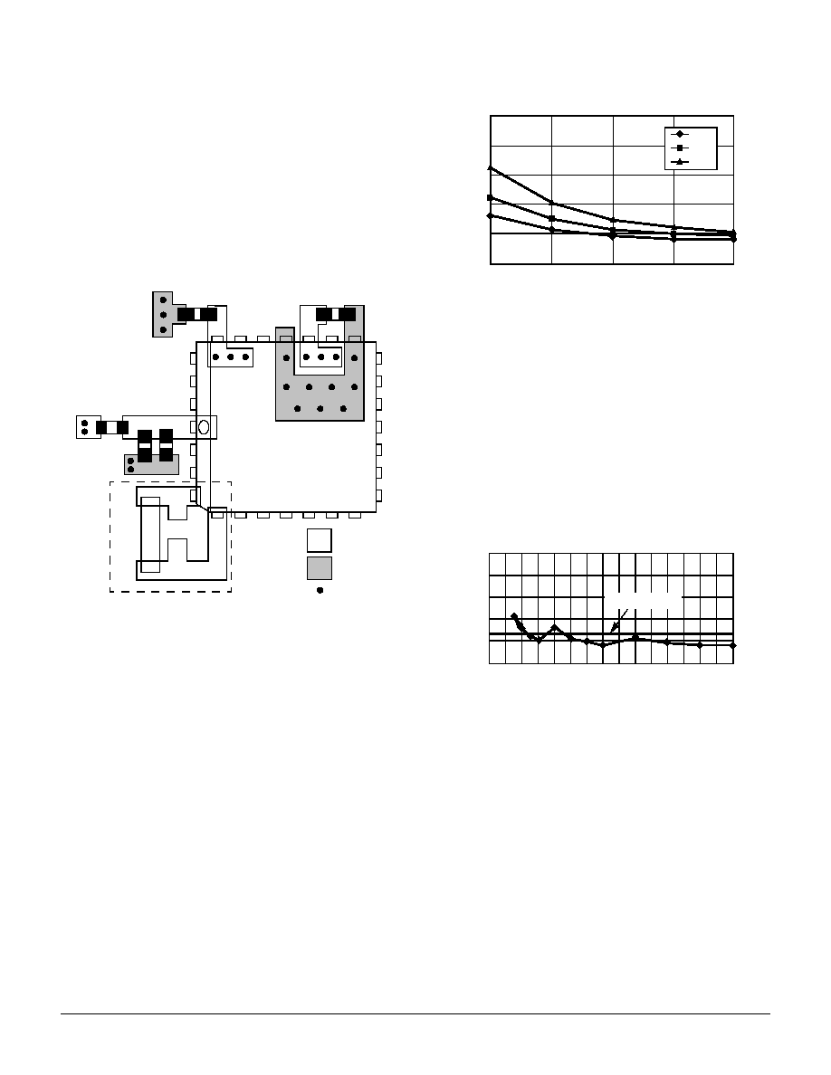
Figure 6. PCB Board Layout for MC12439
Note the dotted lines circling the crystal oscillator connection
to the device. The oscillator is a series resonant circuit, and the
voltage amplitude across the crystal is relatively small. It is
imperative that no actively switching signals cross under the
crystal as crosstalk energy coupled to these lines could
significantly impact the jitter of the device. Special attention
should be paid to the layout of the crystal to ensure a stable,
jitter free interface between the crystal and the on-board
oscillator.
Although the MC12439 has several design features to
minimize the susceptibility to power supply noise (isolated
power and grounds and fully differential PLL), there still may be
applications in which overall performance is being degraded
due to system power supply noise. The power supply filter and
bypass schemes discussed in this section should be adequate
to eliminate power supply noise related problems in most
designs.
Jitter Performance of the MC12439
The MC12439 exhibits long term and cycle-to-cycle jitter
which rivals that of SAW based oscillators. This jitter
performance comes with the added flexibility one gets with a
synthesizer over a fixed frequency oscillator.
Figure 7. RMS PLL Jitter versus VCO Frequency
Figure 7 illustrates the RMS jitter performance of the
MC12439 across its specified VCO frequency range. Note that
the jitter is a function of both the output frequency as well as the
VCO frequency, however the VCO frequency shows a much
stronger dependence. The data presented has not been
compensated for trigger jitter, this fact provides a measure of
guardband to the reported data.
The typical method of measuring the jitter is to accumulate a
large number of cycles, create a histogram of the edge
placements and record peak-to-peak as well as standard
deviations of the jitter. Care must be taken that the measured
edge is the edge immediately following the trigger edge. The
oscilloscope cannot collect adjacent pulses, rather it collects
pulses from a very large sample of pulses.
Figure 8. RMS Jitter versus Output Frequency
Figure 8 shows the jitter as a function of the output
frequency. For the 12439, this information is probably of more
importance. The flat line represents an RMS jitter value that
corresponds to an 8 sigma
±25 ps peak-to-peak long term
period jitter. The graph shows that for output frequencies from
87.5 to 400 MHz the jitter falls within the
±25 ps peak-to-peak
specification. The general trend is that as the output frequency
is decreased, the output edge jitter will increase.
The jitter data from Figure 7 does not include the
performance of the 12439 when the output is in the divide by 1
mode. In divide by one mode, the MC12439 output jitter
distribution is bimodal. Since a bimodal distribution cannot be
accurately represented with an rms value, peak-to-peak values
of jitter for the divide by one mode are presented.
1
C2
C3
R1
Xtal
C1
R1 = 10–15
C1 = 0.01
F
C2 = 22
F
C3 = 0.01
F
= VCC
= GND
= Via
400
500
600
700
800
25
20
15
10
5
0
RMS
Jitter
(ps)
VCO Frequency (MHz)
N=2
N=4
N=8
25
20
15
10
5
0
RMS
Ji
tter
(ps
)
6.25ps Reference
Output Frequency (MHz)
25 50 75 100 125 150 175 200 225250275300 325 350 375 400
相關(guān)PDF資料 |
PDF描述 |
|---|---|
| MC143120E2FB | 1 CHANNEL(S), 1.25M bps, LOCAL AREA NETWORK CONTROLLER, PQFP44 |
| MC143120LE2DWR2 | 1 CHANNEL(S), 1.25M bps, LOCAL AREA NETWORK CONTROLLER, PDSO32 |
| MC143150B1FU | 1 CHANNEL(S), 1.25M bps, LOCAL AREA NETWORK CONTROLLER, PQFP64 |
| MC14411DW | 1.843 MHz, OTHER CLOCK GENERATOR, PDSO24 |
| MC14500BCPD | 1-BIT, 1 MHz, MICROPROCESSOR, PDIP16 |
相關(guān)代理商/技術(shù)參數(shù) |
參數(shù)描述 |
|---|---|
| MC1243F | 制造商:Rochester Electronics LLC 功能描述:- Bulk |
| MC1245L | 制造商:Rochester Electronics LLC 功能描述:- Bulk |
| MC1246L | 制造商:Rochester Electronics LLC 功能描述:- Bulk |
| MC1247F | 制造商:Rochester Electronics LLC 功能描述:- Bulk |
| MC1247L | 制造商:Rochester Electronics LLC 功能描述:- Bulk |
發(fā)布緊急采購,3分鐘左右您將得到回復。