- 您現(xiàn)在的位置:買賣IC網(wǎng) > PDF目錄299463 > MBM29DL161BE-90PBT (FUJITSU LTD) 1M X 16 FLASH 3V PROM, 90 ns, PBGA48 PDF資料下載
參數(shù)資料
| 型號(hào): | MBM29DL161BE-90PBT |
| 廠商: | FUJITSU LTD |
| 元件分類: | PROM |
| 英文描述: | 1M X 16 FLASH 3V PROM, 90 ns, PBGA48 |
| 封裝: | PLASTIC, FBGA-48 |
| 文件頁(yè)數(shù): | 36/76頁(yè) |
| 文件大?。?/td> | 1145K |
| 代理商: | MBM29DL161BE-90PBT |
第1頁(yè)第2頁(yè)第3頁(yè)第4頁(yè)第5頁(yè)第6頁(yè)第7頁(yè)第8頁(yè)第9頁(yè)第10頁(yè)第11頁(yè)第12頁(yè)第13頁(yè)第14頁(yè)第15頁(yè)第16頁(yè)第17頁(yè)第18頁(yè)第19頁(yè)第20頁(yè)第21頁(yè)第22頁(yè)第23頁(yè)第24頁(yè)第25頁(yè)第26頁(yè)第27頁(yè)第28頁(yè)第29頁(yè)第30頁(yè)第31頁(yè)第32頁(yè)第33頁(yè)第34頁(yè)第35頁(yè)當(dāng)前第36頁(yè)第37頁(yè)第38頁(yè)第39頁(yè)第40頁(yè)第41頁(yè)第42頁(yè)第43頁(yè)第44頁(yè)第45頁(yè)第46頁(yè)第47頁(yè)第48頁(yè)第49頁(yè)第50頁(yè)第51頁(yè)第52頁(yè)第53頁(yè)第54頁(yè)第55頁(yè)第56頁(yè)第57頁(yè)第58頁(yè)第59頁(yè)第60頁(yè)第61頁(yè)第62頁(yè)第63頁(yè)第64頁(yè)第65頁(yè)第66頁(yè)第67頁(yè)第68頁(yè)第69頁(yè)第70頁(yè)第71頁(yè)第72頁(yè)第73頁(yè)第74頁(yè)第75頁(yè)第76頁(yè)
MBM29DL16XTE/BE70/90
41
operation. If it is still toggling, the device did not complete the operation successfully, and the system must write
the reset command to return to reading array data.
The remaining scenario is that the system initially determines that the toggle bit is toggling and DQ5 has not
gone high. The system may continue to monitor the toggle bit and DQ5 through successive read cycles,
determining the status as described in the previous paragraph. Alternatively, it may choose to perform other
system tasks. In this case, the system must start at the begining of the algorithm when it returns to determine
the status of the operation. (Refer to “(4) Toggle Bit Algorithm” in sFLOW CHART.)
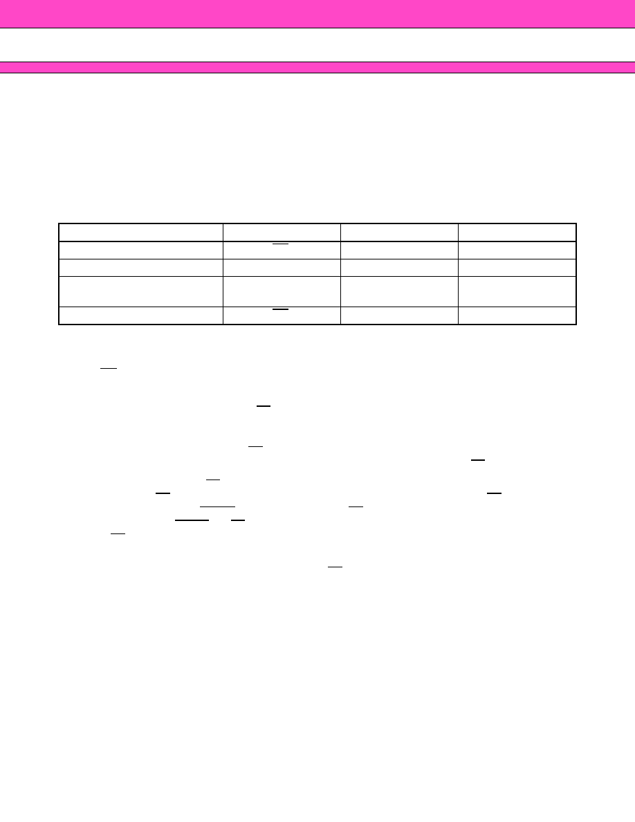
Toggle Bit Status Table
*1 : Successive reads from the erasing or erase-suspend sector cause DQ2 to toggle.
*2 : Reading from the non-erase suspend sector address indicates logic “1” at the DQ2 bit.
RY/BY
Ready/Busy
The MBM29DL16XTE/BE provide a RY/BY open-drain output pin as a way to indicate to the host system that
the Embedded Algorithms are either in progress or has been completed. If the output is low, the devices are
busy with either a program or erase operation. If the output is high, the devices are ready to accept any read/
write or erase operation. When the RY/BY pin is low, the devices will not accept any additional program or erase
commands. If the MBM29DL16XTE/BE are placed in an Erase Suspend mode, the RY/BY output will be high.
During programming, the RY/BY pin is driven low after the rising edge of the fourth write pulse. During an erase
operation, the RY/BY pin is driven low after the rising edge of the sixth write pulse. The RY/BY pin will indicate
a busy condition during the RESET pulse. Refer to “(10) RY/BY Timing Diagram during Program/Erase
Operations” and “(11) RESET, RY/BY Timing Diagram” in sTIMING DIAGRAM for a detailed timing diagram.
The RY/BY pin is pulled high in standby mode.
Since this is an open-drain output, the pull-up resistor needs to be connected to VCC ; multiples of devices may
be connected to the host system via more than one RY/BY pin in parallel.
Data Protection
The MBM29DL16XTE/BE are designed to offer protection against accidental erasure or programming caused
by spurious system level signals that may exist during power transitions. During power up the devices
automatically reset the internal state machine in the Read mode. Also, with its control register architecture,
alteration of the memory contents only occurs after successful completion of specific multi-bus cycle command
sequences.
The devices also incorporate several features to prevent inadvertent write cycles resulting form VCC power-up
and power-down transitions or system noise.
Mode
DQ7
DQ6
DQ2
Program
DQ7
Toggle
1
Erase
0
Toggle
Toggle*1
Erase-Suspend Read
(Erase-Suspended Sector)
11
Toggle
Erase-Suspend Program
DQ7
Toggle
1*2
相關(guān)PDF資料 |
PDF描述 |
|---|---|
| MBM29DL163TD12PBT | 1M X 16 FLASH 3V PROM, 120 ns, PBGA48 |
| MBM29DL32TF70TN | 2M X 16 FLASH 3V PROM, 70 ns, PDSO48 |
| MBM29F800TA-70PFTN-E1 | 512K X 16 FLASH 5V PROM, 70 ns, PDSO48 |
| MBR-2051-1B5T | 51 CONTACT(S), MALE, D MICROMINIATURE CONNECTOR, SOLDER, PLUG |
| MBR-2069-0A1T | 69 CONTACT(S), MALE, D MICROMINIATURE CONNECTOR, SOLDER, PLUG |
相關(guān)代理商/技術(shù)參數(shù) |
參數(shù)描述 |
|---|---|
| MBM29DL161BE-90TN | 制造商:SPANSION 制造商全稱:SPANSION 功能描述:FLASH MEMORY CMOS 16M (2M X 8/1M X 16) BIT Dual Operation |
| MBM29DL161BE-90TR | 制造商:SPANSION 制造商全稱:SPANSION 功能描述:FLASH MEMORY CMOS 16M (2M X 8/1M X 16) BIT Dual Operation |
| MBM29DL161TD | 制造商:FUJITSU 制造商全稱:Fujitsu Component Limited. 功能描述:16M (2M x 8/1M x 16) BIT Dual Operation |
| MBM29DL161TD-70PBT | 制造商:SPANSION 制造商全稱:SPANSION 功能描述:FLASH MEMORY CMOS 16M (2M X 8/1M X 16) BIT Dual Operation |
| MBM29DL161TD-70PFTN | 制造商:SPANSION 制造商全稱:SPANSION 功能描述:FLASH MEMORY CMOS 16M (2M X 8/1M X 16) BIT Dual Operation |
發(fā)布緊急采購(gòu),3分鐘左右您將得到回復(fù)。