- 您現(xiàn)在的位置:買賣IC網(wǎng) > PDF目錄384688 > MAX5863ETM (MAXIM INTEGRATED PRODUCTS INC) 5V High-Speed RS-232 Transceivers with 0.1uF Capacitors PDF資料下載
參數(shù)資料
| 型號: | MAX5863ETM |
| 廠商: | MAXIM INTEGRATED PRODUCTS INC |
| 元件分類: | 無繩電話/電話 |
| 英文描述: | 5V High-Speed RS-232 Transceivers with 0.1uF Capacitors |
| 中文描述: | TELECOM, CELLULAR, RF AND BASEBAND CIRCUIT, QCC48 |
| 封裝: | 7 X 7 MM, 0.80 MM HEIGHT, TQFN-48 |
| 文件頁數(shù): | 23/26頁 |
| 文件大?。?/td> | 1673K |
| 代理商: | MAX5863ETM |
第1頁第2頁第3頁第4頁第5頁第6頁第7頁第8頁第9頁第10頁第11頁第12頁第13頁第14頁第15頁第16頁第17頁第18頁第19頁第20頁第21頁第22頁當(dāng)前第23頁第24頁第25頁第26頁

M
Ultra-Low-Power, High-Dynamic
Performance, 7.5Msps Analog Front End
ADC Offset Error
Ideally, the midscale transition occurs at 0.5 LSB above
midscale. The offset error is the amount of deviation
between the measured transition point and the ideal
transition point.
DAC Offset Error
Offset error is the difference between the ideal and
actual offset point. The offset point is the output value
when the digital input is midscale. This error affects all
codes by the same amount and usually can be com-
pensated by trimming.
ADC Gain Error
Ideally, the ADC full-scale transition occurs at 1.5 LSB
below full scale. The gain error is the amount of devia-
tion between the measured transition point and the
ideal transition point with the offset error removed.
ADC Dynamic Parameter Definitions
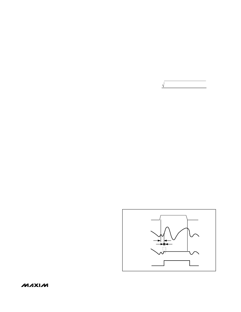
Aperture Jitter
Figure 13
depicts the aperture jitter (t
AJ
), which is the
sample-to-sample variation in the aperture delay.
Aperture Delay
Aperture delay (t
AD
) is the time defined between the
rising edge of the sampling clock and the instant when
an actual sample is taken (
Figure 13
).
Signal-to-Noise Ratio (SNR)
For a waveform perfectly reconstructed from digital
samples, the theoretical maximum SNR is the ratio of
the full-scale analog input (RMS value) to the RMS
quantization error (residual error) and results directly
from the ADC
’
s resolution (N bits):
SNR(max) = 6.02dB x N + 1.76dB (in dB)
In reality, there are other noise sources besides quanti-
zation noise: thermal noise, reference noise, clock jitter,
etc. SNR is computed by taking the ratio of the RMS
signal to the RMS noise. RMS noise includes all spec-
tral components to the Nyquist frequency excluding the
fundamental, the first five harmonics, and the DC offset.
Signal-to-Noise Plus Distortion (SINAD)
SINAD is computed by taking the ratio of the RMS sig-
nal to the RMS noise. RMS noise includes all spectral
components to the Nyquist frequency excluding the
fundamental and the DC offset.
Effective Number of Bits (ENOB)
ENOB specifies the dynamic performance of an ADC at a
specific input frequency and sampling rate. An ideal
ADC
’
s error consists of quantization noise only. ENOB for
a full-scale sinusoidal input waveform is computed from:
ENOB = (SINAD - 1. 76) / 6.02
Total Harmonic Distortion (THD)
THD is typically the ratio of the RMS sum of the first five
harmonics of the input signal to the fundamental itself.
This is expressed as:
where V
1
is the fundamental amplitude and V
2
–
V
6
are
the amplitudes of the 2nd- through 6th-order harmon-
ics.
Third Harmonic Distortion (HD3)
HD3 is defined as the ratio of the RMS value of the third
harmonic component to the fundamental input signal.
Spurious-Free Dynamic Range (SFDR)
SFDR is the ratio expressed in decibels of the RMS
amplitude of the fundamental (maximum signal compo-
nent) to the RMS value of the next-largest spurious
component, excluding DC offset.
Intermodulation Distortion (IMD)
IMD is the total power of the intermodulation products
relative to the total input power when two tones, f
1
and
f
2
, are present at the inputs. The intermodulation prod-
ucts are (f
1
±f
2
), (2
f
1
), (2
f
2
), (2
f
1
±f
2
), (2
f
2
±f
1
). The individual input tone levels are at -7dBFS.
3rd-Order Intermodulation (IM3)
IM3 is the power of the worst third-order intermodula-
tion product relative to the input power of either input
tone when two tones, f
1
and f
2
, are present at the
inputs. The 3rd-order intermodulation products are (2 x
f
1
±f
2
), (2
f
2
±f
1
). The individual input tone levels are
at -7dBFS.
THD
(V +V +V +V +V )
V
1
=
20log
HOLD
ANALOG
INPUT
SAMPLED
DATA (T/H)
T/H
t
AD
t
AJ
TRACK
TRACK
CLK
Figure 13. T/H Aperture Timing
______________________________________________________________________________________________________
23
相關(guān)PDF資料 |
PDF描述 |
|---|---|
| MAX5864 | Quadruple Differential Line Receiver 16-CDIP -55 to 125 |
| MAX5864ETM | Ultra-Low-Power, High-Dynamic- Performance, 22Msps Analog Front End |
| MAX5865 | Ultra-Low-Power, High-Dynamic- Performance, 40Msps Analog Front End |
| MAX5865ETM | Ultra-Low-Power, High-Dynamic- Performance, 40Msps Analog Front End |
| MAX5873 | Quadruple Line Driver 14-CDIP -55 to 125 |
相關(guān)代理商/技術(shù)參數(shù) |
參數(shù)描述 |
|---|---|
| MAX5863ETM+ | 功能描述:ADC / DAC多通道 10-Bit 2Ch 7.5Msps CODEC/AFE RoHS:否 制造商:Texas Instruments 轉(zhuǎn)換速率: 分辨率:8 bit 接口類型:SPI 電壓參考: 電源電壓-最大:3.6 V 電源電壓-最小:2 V 最大工作溫度:+ 85 C 安裝風(fēng)格:SMD/SMT 封裝 / 箱體:VQFN-40 |
| MAX5863ETM+T | 功能描述:ADC / DAC多通道 RoHS:否 制造商:Texas Instruments 轉(zhuǎn)換速率: 分辨率:8 bit 接口類型:SPI 電壓參考: 電源電壓-最大:3.6 V 電源電壓-最小:2 V 最大工作溫度:+ 85 C 安裝風(fēng)格:SMD/SMT 封裝 / 箱體:VQFN-40 |
| MAX5863ETM-T | 功能描述:ADC / DAC多通道 RoHS:否 制造商:Texas Instruments 轉(zhuǎn)換速率: 分辨率:8 bit 接口類型:SPI 電壓參考: 電源電壓-最大:3.6 V 電源電壓-最小:2 V 最大工作溫度:+ 85 C 安裝風(fēng)格:SMD/SMT 封裝 / 箱體:VQFN-40 |
| MAX5864ETM | 功能描述:ADC / DAC多通道 RoHS:否 制造商:Texas Instruments 轉(zhuǎn)換速率: 分辨率:8 bit 接口類型:SPI 電壓參考: 電源電壓-最大:3.6 V 電源電壓-最小:2 V 最大工作溫度:+ 85 C 安裝風(fēng)格:SMD/SMT 封裝 / 箱體:VQFN-40 |
| MAX5864ETM+ | 功能描述:ADC / DAC多通道 10-Bit 2Ch 22Msps CODEC/AFE RoHS:否 制造商:Texas Instruments 轉(zhuǎn)換速率: 分辨率:8 bit 接口類型:SPI 電壓參考: 電源電壓-最大:3.6 V 電源電壓-最小:2 V 最大工作溫度:+ 85 C 安裝風(fēng)格:SMD/SMT 封裝 / 箱體:VQFN-40 |
發(fā)布緊急采購,3分鐘左右您將得到回復(fù)。