- 您現(xiàn)在的位置:買賣IC網(wǎng) > PDF目錄299460 > MAX16049ATN+ (MAXIM INTEGRATED PRODUCTS INC) 8-CHANNEL POWER SUPPLY MANAGEMENT CKT, QCC56 PDF資料下載
參數(shù)資料
| 型號(hào): | MAX16049ATN+ |
| 廠商: | MAXIM INTEGRATED PRODUCTS INC |
| 元件分類: | 電源管理 |
| 英文描述: | 8-CHANNEL POWER SUPPLY MANAGEMENT CKT, QCC56 |
| 封裝: | 8 X 8 MM, ROHS COMPLIANT, TQFN-56 |
| 文件頁(yè)數(shù): | 8/61頁(yè) |
| 文件大?。?/td> | 790K |
| 代理商: | MAX16049ATN+ |
第1頁(yè)第2頁(yè)第3頁(yè)第4頁(yè)第5頁(yè)第6頁(yè)第7頁(yè)當(dāng)前第8頁(yè)第9頁(yè)第10頁(yè)第11頁(yè)第12頁(yè)第13頁(yè)第14頁(yè)第15頁(yè)第16頁(yè)第17頁(yè)第18頁(yè)第19頁(yè)第20頁(yè)第21頁(yè)第22頁(yè)第23頁(yè)第24頁(yè)第25頁(yè)第26頁(yè)第27頁(yè)第28頁(yè)第29頁(yè)第30頁(yè)第31頁(yè)第32頁(yè)第33頁(yè)第34頁(yè)第35頁(yè)第36頁(yè)第37頁(yè)第38頁(yè)第39頁(yè)第40頁(yè)第41頁(yè)第42頁(yè)第43頁(yè)第44頁(yè)第45頁(yè)第46頁(yè)第47頁(yè)第48頁(yè)第49頁(yè)第50頁(yè)第51頁(yè)第52頁(yè)第53頁(yè)第54頁(yè)第55頁(yè)第56頁(yè)第57頁(yè)第58頁(yè)第59頁(yè)第60頁(yè)第61頁(yè)
MAX16047A/MAX16049A
12-Channel/8-Channel EEPROM-Programmable
System Managers with Nonvolatile Fault Registers
16
______________________________________________________________________________________
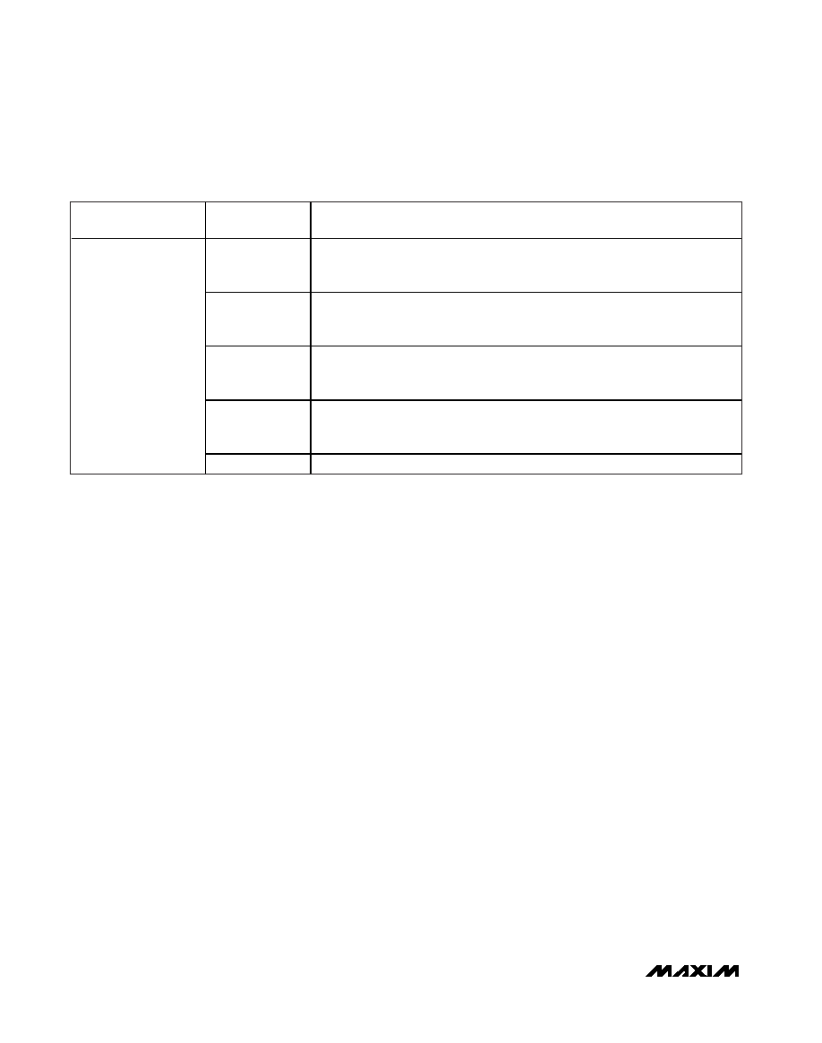
Table 1. EEPROM Software Enable Configurations
REGISTER/
EEPROM ADDRESS
BIT RANGE
DESCRIPTION
0
Software Enable bit
0 = Enabled. EN must also be high to begin sequencing
1 = Disabled (factory default)
1
Margin bit
1 = Margin functionality is enabled
0 = Margin disabled
2
Early Warning Selection bit
0 = Early warning thresholds are undervoltage thresholds
1 = Early warning thresholds are overvoltage thresholds
3
Watchdog Mode Selection bit
0 = Watchdog timer is in dependent mode
1 = Watchdog timer is in independent mode
4Dh
[7:4]
Not used
Enable
To initiate sequencing/tracking and enable monitoring,
the voltage at EN must be above 0.525V and the
Software Enable bit in r4Dh[0] must be set to ‘0.’ To
power down and disable monitoring, either pull EN
below 0.5V or set the Software Enable bit to ‘1.’ See
Table 1 for the software enable bit configurations.
Connect EN to ABP if not used.
If a fault condition occurs during the power-up cycle,
the EN_OUT_ outputs are powered down immediately,
independent of the state of EN. If operating in latch-on
fault mode, toggle EN or toggle the Software Enable bit
to clear the latch condition and restart the device once
the fault condition has been removed. If EN is driven by
external logic instead of from the center tap of a VCC-
connected resistive divider, ensure that an active-high
pulse occurs on EN within 1.5ms of VCC exceeding
2.85V. If the external driving logic is in the high-imped-
ance state during power-up, this pulse can be created
by connecting an external pullup resistor to EN.
Voltage Monitoring
The MAX16047A/MAX16049A feature an internal 10-bit
ADC that monitors the MON_ voltage inputs. An internal
multiplexer cycles through each of the twelve inputs,
taking 150s (typ) for a complete monitoring cycle.
Each acquisition takes approximately 12.45s. At each
multiplexer stop, the 10-bit ADC converts the analog
input to a digital result and stores the result in a regis-
ter. ADC conversion results are stored in registers r00h
to r17h in the extended page. Use the I2C or JTAG seri-
al interface to read ADC conversion results. See the
I2C/SMBus-Compatible Serial Interface or the JTAG
Serial Interface section for more information on access-
ing the extended page.
The MAX16047A provides twelve inputs, MON1–MON12,
for voltage monitoring. The MAX16049A provides eight
inputs, MON1–MON8, for voltage monitoring. Each input
voltage range is programmable in registers r0Fh to r11h
(see Table 2). When MON_ configuration registers are set
to ‘11,’ MON_ voltages are not monitored or converted,
and the multiplexer does not stop at these inputs,
decreasing the total cycle time. These inputs cannot be
configured to trigger fault conditions.
The three programmable thresholds for each monitored
voltage include an overvoltage, an undervoltage, and
an early warning threshold that can be set in r4Dh[2] to
be either an undervoltage or overvoltage threshold. See
the
Faults section for more information on setting over-
voltage and undervoltage thresholds. All voltage
thresholds are 8 bits wide. The 8 MSBs of the 10-bit
ADC conversion result are compared to these overvolt-
age and undervoltage thresholds.
For any undervoltage or overvoltage condition to be
monitored and any faults detected, the MON_ input
must be assigned to a particular sequence order. See
the
Sequencing section for more details on assigning
MON_ inputs.
相關(guān)PDF資料 |
PDF描述 |
|---|---|
| MAX2042AETP+T | TELECOM, CELLULAR, RF AND BASEBAND CIRCUIT, QCC20 |
| MAX2042AETP+ | TELECOM, CELLULAR, RF AND BASEBAND CIRCUIT, QCC20 |
| MAX2102CWI | Direct-Conversion Tuner ICs for Digital DBS Applications |
| MAX3202EEBT-T | UNIDIRECTIONAL, 4 ELEMENT, SILICON, TVS DIODE |
| MAX359MJE | Fault-Protected Analog Multiplexer |
相關(guān)代理商/技術(shù)參數(shù) |
參數(shù)描述 |
|---|---|
| MAX16049ATN+ | 功能描述:監(jiān)控電路 8Ch EEPROM Prob System Manager RoHS:否 制造商:STMicroelectronics 監(jiān)測(cè)電壓數(shù): 監(jiān)測(cè)電壓: 欠電壓閾值: 過(guò)電壓閾值: 輸出類型:Active Low, Open Drain 人工復(fù)位:Resettable 監(jiān)視器:No Watchdog 電池備用開(kāi)關(guān):No Backup 上電復(fù)位延遲(典型值):10 s 電源電壓-最大:5.5 V 最大工作溫度:+ 85 C 安裝風(fēng)格:SMD/SMT 封裝 / 箱體:UDFN-6 封裝:Reel |
| MAX16049ATN+T | 功能描述:監(jiān)控電路 8Ch EEPROM Prob System Manager RoHS:否 制造商:STMicroelectronics 監(jiān)測(cè)電壓數(shù): 監(jiān)測(cè)電壓: 欠電壓閾值: 過(guò)電壓閾值: 輸出類型:Active Low, Open Drain 人工復(fù)位:Resettable 監(jiān)視器:No Watchdog 電池備用開(kāi)關(guān):No Backup 上電復(fù)位延遲(典型值):10 s 電源電壓-最大:5.5 V 最大工作溫度:+ 85 C 安裝風(fēng)格:SMD/SMT 封裝 / 箱體:UDFN-6 封裝:Reel |
| MAX16049ETN+ | 功能描述:監(jiān)控電路 8Ch EEPROM Prob System Manager RoHS:否 制造商:STMicroelectronics 監(jiān)測(cè)電壓數(shù): 監(jiān)測(cè)電壓: 欠電壓閾值: 過(guò)電壓閾值: 輸出類型:Active Low, Open Drain 人工復(fù)位:Resettable 監(jiān)視器:No Watchdog 電池備用開(kāi)關(guān):No Backup 上電復(fù)位延遲(典型值):10 s 電源電壓-最大:5.5 V 最大工作溫度:+ 85 C 安裝風(fēng)格:SMD/SMT 封裝 / 箱體:UDFN-6 封裝:Reel |
| MAX16049ETN+T | 功能描述:監(jiān)控電路 8Ch EEPROM Prob System Manager RoHS:否 制造商:STMicroelectronics 監(jiān)測(cè)電壓數(shù): 監(jiān)測(cè)電壓: 欠電壓閾值: 過(guò)電壓閾值: 輸出類型:Active Low, Open Drain 人工復(fù)位:Resettable 監(jiān)視器:No Watchdog 電池備用開(kāi)關(guān):No Backup 上電復(fù)位延遲(典型值):10 s 電源電壓-最大:5.5 V 最大工作溫度:+ 85 C 安裝風(fēng)格:SMD/SMT 封裝 / 箱體:UDFN-6 封裝:Reel |
| MAX1604EAI | 功能描述:電源開(kāi)關(guān) IC - 配電 RoHS:否 制造商:Exar 輸出端數(shù)量:1 開(kāi)啟電阻(最大值):85 mOhms 開(kāi)啟時(shí)間(最大值):400 us 關(guān)閉時(shí)間(最大值):20 us 工作電源電壓:3.2 V to 6.5 V 電源電流(最大值): 最大工作溫度:+ 85 C 安裝風(fēng)格:SMD/SMT 封裝 / 箱體:SOT-23-5 |
發(fā)布緊急采購(gòu),3分鐘左右您將得到回復(fù)。