- 您現(xiàn)在的位置:買賣IC網(wǎng) > PDF目錄384606 > LP5551SQX (NATIONAL SEMICONDUCTOR CORP) PowerWise⑩ Technology Compliant Energy Management Unit PDF資料下載
參數(shù)資料
| 型號: | LP5551SQX |
| 廠商: | NATIONAL SEMICONDUCTOR CORP |
| 元件分類: | 模擬信號調(diào)理 |
| 英文描述: | PowerWise⑩ Technology Compliant Energy Management Unit |
| 中文描述: | SPECIALTY ANALOG CIRCUIT, QCC36 |
| 封裝: | LLP-36 |
| 文件頁數(shù): | 27/32頁 |
| 文件大小: | 3081K |
| 代理商: | LP5551SQX |
第1頁第2頁第3頁第4頁第5頁第6頁第7頁第8頁第9頁第10頁第11頁第12頁第13頁第14頁第15頁第16頁第17頁第18頁第19頁第20頁第21頁第22頁第23頁第24頁第25頁第26頁當(dāng)前第27頁第28頁第29頁第30頁第31頁第32頁
Application Information
PWM/PFM FORCE REGISTER (R9)
By default, the LP5551 automatically transitions between
PFM and PWM to optimize efficiency. The PWM/PFM force
register (R9) provides the option to override the automatic
transition and force PFM or PWM operation (see R9 – PWM/
PFM Force Register declaration). Note that if the operating
mode of the regulator is forced to be PFM then the switch
current limit is reduced to 100 mA (50 mA average load cur-
rent).
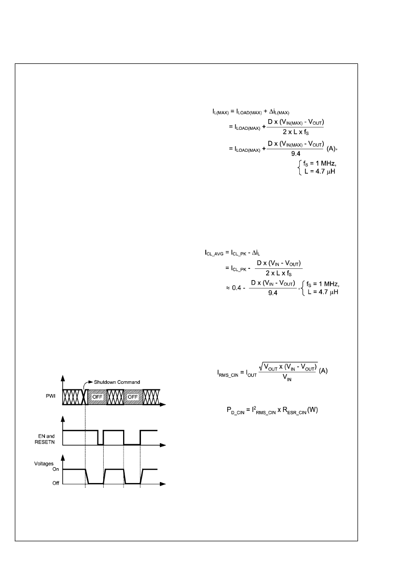
EN/RESETN
The LP5551 can be shutdown via the ENABLE or RESETN
pins, or by issuing a shutdown command from PWI. To dis-
able the LP5551 via hardware (as opposed to the PWI shut-
down command), pull the ENABLE and/or the RESETN pin
(s) low. To enable the LP5551, both the ENABLE and the
RESETN pins must be high. Once enabled, the LP5551 en-
gages the power-up sequence and all voltages return to their
default values.
When using PWI to issue a shutdown command, the PWI will
be disabled along with the regulators in the LP5551. To re-
enable the part, either the ENABLE, RESETN, or both pins
must be toggled (high – low – high). The part will then enter
the power-up sequence and all voltages will return to their
default values.
Figure 8
summarizes the ENABLE/RESETN
control.
The ENABLE and RESETN pins provide flexibility for system
control. In larger systems such as a mobile phone, it can be
advantageous to enable/disable a subsystem independently.
For example, the LP5551 may be powering the applications
processor in a mobile phone. The system controller can pow-
er down the applications processor via the ENABLE pin, but
leave on other subsystems. When the phone is turned off or
in a fault condition, the system controller can have a global
reset command that is connected to all the subsystems (RE-
SETN for the LP5551). However, if this type of control is not
needed, the ENABLE and RESETN pins can be tied together
and used as a single enable/disable pin.
20172151
FIGURE 8. ENABLE and RESETN operation
INDUCTOR
A 4.7uH inductor should be used with the LP5551. The in-
ductor should be rated to handle the peak load current plus
the ripple current:
CURRENT LIMIT
The switching converter in the LP5551 detects the peak in-
ductor current and limits it for protection (see Electrical Char-
acteristics table and/or Typical Performance section). To
determine the average current limit from the peak current lim-
it, the inductor size, input and output voltage, and switching
frequency must be known. The LP5551 is designed to work
with a 4.7uH inductor, so:
INPUT CAPACITOR
The input capacitor to the switching converter supplies the AC
switching current drawn from the switching action of the in-
ternal power FETs. The input current of a buck converter is
discontinuous, so the ripple current supplied by the input ca-
pacitor is large. The input capacitor must be rated to handle
this current:
The power dissipated in the input capacitor is given by:
The input capacitor must be rated to handle both the RMS
current and the dissipated power. A 22 μF ceramic capacitor
is recommended for the LP5551.
OUTPUT CAPACITOR
The switching converters in the LP5551 are designed to be
used with a 22uF ceramic output capacitor. The dielectric
should be X5R, X7R, or comparable material to maintain
proper tolerances. The output capacitor of the switching con-
verter absorbs the AC ripple current from the inductor and
provides the initial response to a load transient. The ripple
voltage at the output of the converter is the product of the
ripple current flowing through the output capacitor and the
impedance of the capacitor. The impedance of the capacitor
can be dominated by capacitive, resistive, or inductive ele-
ments within the capacitor, depending on the frequency of the
27
www.national.com
L
相關(guān)PDF資料 |
PDF描述 |
|---|---|
| LPBC4-3 | POWR-BLOKS Distribution/Splicer Blocks and Covers |
| LPBC5-1 | POWR-BLOKS Distribution/Splicer Blocks and Covers |
| LPBC5-2 | POWR-BLOKS Distribution/Splicer Blocks and Covers |
| LPBC5-3 | POWR-BLOKS Distribution/Splicer Blocks and Covers |
| LPBC0-3 | POWR-BLOKS Distribution/Splicer Blocks and Covers |
相關(guān)代理商/技術(shù)參數(shù) |
參數(shù)描述 |
|---|---|
| LP5551SQX/NOPB | 功能描述:PMIC 解決方案 RoHS:否 制造商:Texas Instruments 安裝風(fēng)格:SMD/SMT 封裝 / 箱體:QFN-24 封裝:Reel |
| LP5552 | 制造商:NSC 制造商全稱:National Semiconductor 功能描述:PWI 2.0 and PowerWise Technology Compliant Energy Management Unit |
| LP5552_08 | 制造商:NSC 制造商全稱:National Semiconductor 功能描述:PWI 2.0 and PowerWise Technology Compliant Energy Management Unit |
| LP5552TL/NOPB | 功能描述:PMIC 解決方案 RoHS:否 制造商:Texas Instruments 安裝風(fēng)格:SMD/SMT 封裝 / 箱體:QFN-24 封裝:Reel |
| LP5552TLEV | 功能描述:電源管理IC開發(fā)工具 LP5552TL EVAL BOARD RoHS:否 制造商:Maxim Integrated 產(chǎn)品:Evaluation Kits 類型:Battery Management 工具用于評估:MAX17710GB 輸入電壓: 輸出電壓:1.8 V |
發(fā)布緊急采購,3分鐘左右您將得到回復(fù)。