- 您現(xiàn)在的位置:買賣IC網(wǎng) > PDF目錄384602 > LM9812CCV (NATIONAL SEMICONDUCTOR CORP) LM9812 30-Bit Color Linear CCD Sensor Processor PDF資料下載
參數(shù)資料
| 型號: | LM9812CCV |
| 廠商: | NATIONAL SEMICONDUCTOR CORP |
| 元件分類: | 模擬信號調理 |
| 英文描述: | LM9812 30-Bit Color Linear CCD Sensor Processor |
| 中文描述: | SPECIALTY ANALOG CIRCUIT, PQCC52 |
| 封裝: | PLASTIC, LCC-52 |
| 文件頁數(shù): | 28/37頁 |
| 文件大小: | 479K |
| 代理商: | LM9812CCV |
第1頁第2頁第3頁第4頁第5頁第6頁第7頁第8頁第9頁第10頁第11頁第12頁第13頁第14頁第15頁第16頁第17頁第18頁第19頁第20頁第21頁第22頁第23頁第24頁第25頁第26頁第27頁當前第28頁第29頁第30頁第31頁第32頁第33頁第34頁第35頁第36頁第37頁
28
http://www.national.com
This PGA is static - it does not change at the pixel rate. The Pixel-
Rate Shading Multiplier is used to eliminate pixel-to-pixel gain
errors (typically sensor PRNU and shading errors).
1.2.2 Static Offset DACs
The Static Offset DACs remove DC offsets generated by the sen-
sor and the LM9812’s analog signal chain. The DACs should be
set during calibration to the lowest value that still results in an
ADC output code > 0 for all the pixels. Each LSB of the offset
DAC is typically 4.2 ADC LSBs, providing a total offset adjust-
ment range of ±130 ADC LSBs. The equation for the offset DAC
is:
Like the PGA, the Offset DAC is static - it does not change at the
pixel rate. The Pixel Rate Offset Subtractor is used to eliminate
pixel-to-pixel offset errors.
1.2.3 ADC
The 10 bit ADC quantizes the output from the analog chain and
passes the result to the digital section for pixel rate error correc-
tion. The ADC’s input range is equal to V
REF IN
/C, where C is the
gain constant compensating for all sources of gain error through-
out the entire analog signal path.
1.3 DIGITAL SIGNAL PATH
1.3.1 Pixel-Rate Offset Subtractor
The output of the ADC is fed to the Pixel-Rate Offset Subtractor.
Each pixel of image data may have a different offset error. If bit 0
of Register 9 is set to a 0 and a byte representing the offset error
code is fed to the Pixel-Rate Offset Subtractor through the CD0-
CD9 databus, the offset for each pixel can be subtracted from the
ADC output code at the pixel conversion rate. If this feature is not
desired, the Offset Subtractor can be set to a fixed value by writ-
ing the desired value to Register 6 and setting bit 0 of Register 9
to a 1.
The offset subtractor input is 8 bits wide, input on CD0-CD7, for a
correction range of 0 to 255. Information on bits CD8 and CD9 is
ignored.
1.3.2 Pixel-Rate Shading Multiplier
The Pixel Rate Shading Multiplier follows the Offset Subtractor.
This stage compensates for nonuniformities between individual
pixels (shading error). Each pixel of image data may have a differ-
ent gain error. If bit 1 of Register 9 is set to a 0 and a word repre-
senting the gain correction coefficient is fed to the Pixel-Rate
Shading Multiplier through the CD0-CD9 databus, the gain for
each pixel is changed at the pixel rate to eliminate pixel-to-pixel
gain errors. If this feature is not desired, the Shading Multiplier
can be set to a fixed value by writing the desired gain value to
Registers 7 and 8 and setting bit 1 of Register 9 to a 1.
The equation for calculating the gain of the multiplier is given in
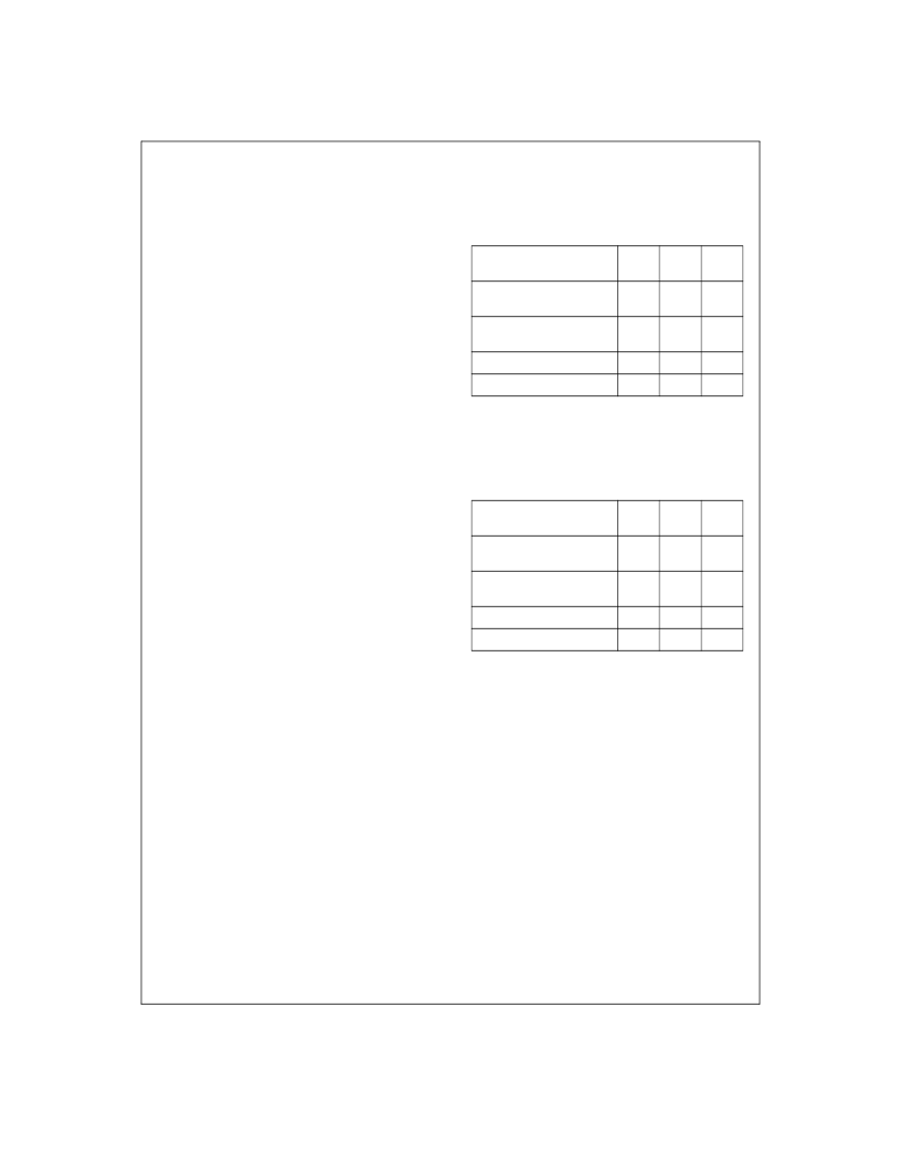
Equation 5. The Pixel Rate Shading Multiplier has three different
gain ranges as shown in
Table 1
. For systems where the ratio of
the strongest pixel to the weakest pixel is less than 1.5, the multi-
plier gain range setting of 1:1.5 provides very accurate control of
the gain of each pixel. Systems with larger variation can use gain
ranges of 1:2 or 1:3.
When the 8 bit Coefficient Bus Width is selected (Register 25, bit
6=1), the coefficient data is only 8 bits wide, supplied on CD0-
CD7. This reduces the accuracy of the gain correction, but allows
the use of an 8 bit path to store coefficient data, instead of a 10 or
16 bit wide path.
1.4 SENSOR CLOCK GENERATION
The LM9812 generates all of the clock signals required to directly
drive most commercial linear CCDs and some CIS - no external
clock buffers are necessary. Most linear CCDs designed for scan-
ner applications require 0 to 5V signal swings into 20 to 500pF
input loading. Series resistors are typically inserted between the
driver and the CCD to control slew rate and isolate the driver from
the large load capacitances. The values of these resistors are
given in the CCD’s datasheet.
1.4.1 TR1 and TR2
The LM9812 supports one or two TR (transfer, or shift) pulses as
shown in Diagrams 8 and 9. This pulse is used to transfer the
contents of each pixel’s photodiode to the CCD’s serial shift regis-
ter for clocking out of the CCD. Configuration Registers 16, 17,
and 18 control the TR1, TR2, and TR guardband pulse widths,
while Register 24, bit 3 determines whether the LM9812 gener-
ates TR1 only or both TR1 and TR2 at the beginning of a line.
The polarities of the TR pulses are determined by Register 26,
bits 2 and 3. If not needed, one or both TR pulses can be dis-
abled by setting Register 25, bits 3 and 4 to the appropriate value.
Offset ADC LSBs
Equation 3: Offset DAC
)
4.2 DAC Code
)
=
Offset Subtractor Out
ADC Output
Offset Error Code
–
=
Equation 4: Offset Subtractor
Multiplier Gain Range
1:1.5
(33%)
1:2.0
(50%)
1:3.0
(67%)
Minimum Gain
(V/V, Multiplier Input = 0)
1
1
1
Maximum Gain
(V/V, Multiplier Input = 1024)
1.5
2.0
3.0
N (used in Equation 5)
2048
1024
512
Bits D3, D2 of Register 9
1, 0
0, 1
0,0
Table 1:Shading Multiplier: 10 bit Coefficient Bus Width
Multiplier Gain Range
1:1.5
(33%)
1:2.0
(50%)
1:3.0
(67%)
Minimum Gain
(V/V, Multiplier Input = 0)
1
1
1
Maximum Gain
(V/V, Multiplier Input = 256)
1.5
2.0
3.0
N (used in Equation 5)
512
256
128
Bits D3, D2 of Register 9
1, 0
0, 1
0,0
Table 2:Shading Multiplier: 8 bit Coefficient Bus Width
Multiplier Gain(V/V)
1
Gain CorrectN
+
=
Equation 5: Shading Multiplier Gain
相關PDF資料 |
PDF描述 |
|---|---|
| LM9823CCWM | LM9823 3 Channel 48-Bit Color Scanner Analog Front End |
| LM9823CCWMX | LM9823 3 Channel 48-Bit Color Scanner Analog Front End |
| LMC13204 | Quad SPST High Voltage CMOS Analog Switches |
| LMC13334 | Quad SPST High Voltage CMOS Analog Switches |
| LMC13335 | Quad SPST High Voltage CMOS Analog Switches |
相關代理商/技術參數(shù) |
參數(shù)描述 |
|---|---|
| LM981-SC36 | 功能描述:基本/快動開關 Foot Switch RoHS:否 制造商:Omron Electronics 觸點形式:SPDT 執(zhí)行器:Lever 電流額定值:5 A 電壓額定值 AC:250 V 電壓額定值 DC:30 V 功率額定值: 工作力:120 g IP 等級:IP 67 NEMA 額定值: 端接類型:Wire 安裝:Panel |
| LM981-ZZ | 功能描述:基本/快動開關 Foot Switch RoHS:否 制造商:Omron Electronics 觸點形式:SPDT 執(zhí)行器:Lever 電流額定值:5 A 電壓額定值 AC:250 V 電壓額定值 DC:30 V 功率額定值: 工作力:120 g IP 等級:IP 67 NEMA 額定值: 端接類型:Wire 安裝:Panel |
| LM981-ZZ-1 | 功能描述:基本/快動開關 Foot Switch RoHS:否 制造商:Omron Electronics 觸點形式:SPDT 執(zhí)行器:Lever 電流額定值:5 A 電壓額定值 AC:250 V 電壓額定值 DC:30 V 功率額定值: 工作力:120 g IP 等級:IP 67 NEMA 額定值: 端接類型:Wire 安裝:Panel |
| LM9820 | 制造商:未知廠家 制造商全稱:未知廠家 功能描述: |
| LM9820CCWM | 制造商:NSC 制造商全稱:National Semiconductor 功能描述:LM9810/20 10/12-Bit Image Sensor Processor Analog Front End |
發(fā)布緊急采購,3分鐘左右您將得到回復。