- 您現(xiàn)在的位置:買賣IC網(wǎng) > PDF目錄384588 > L9942 (意法半導(dǎo)體) Super Smart Motor Bridge Driver(電機橋驅(qū)動器) PDF資料下載
參數(shù)資料
| 型號: | L9942 |
| 廠商: | 意法半導(dǎo)體 |
| 英文描述: | Super Smart Motor Bridge Driver(電機橋驅(qū)動器) |
| 中文描述: | 超級智能電機橋式驅(qū)動器(電機橋驅(qū)動器) |
| 文件頁數(shù): | 6/21頁 |
| 文件大小: | 160K |
| 代理商: | L9942 |
ing edge causes an interrupt request on the interrupt line #0. If the overvoltage situation is still present,
OV is SETagain. The bridge is switched off automaticallyat overvoltage.
UNV:
This bit is SET as soon as the voltage on VS pin falls below the undervoltage threshold V
smin
.
This rising edge causes a interrupt request on the interrupt line #0. This bit is RESET by softwareonly. If
the undervoltagesituationis still present, UNV remainsSET. The bridge is not switched off automatically
at undervoltage.
OVT1:
This bit is SET as soon as the temperature of the chip exceeds 130
°
C. This rising edge causes
an interrupt request on the interrupt line #0. This bit is RESET by software only. If the overtemperature
situation is still present,
OVT1
remains SET. The bridge is not switched off automatically at overtem-
perature.
OVT2:
This bit is SET as soon as the temperature of the chip exceeds 150
°
C. This rising edge causes
an interrupt request on the interrupt line #0. This bit is RESET by software only. If the overtemperature
situation is still present,
OVT2
remains SET. The bridge is not switched off automatically at overtem-
perature.
Warning:
All power bridge flags are ored to form one interrupt request which is connected to edge sen-
sitive interrupt input #0 (see Fig. 11). The interrupt request is stored in a flipflop which is automatically
cleared when the interrupt service routine is entered. If other interrupt flags of the power bridge become
active before the flag which caused the interrupt is cleared by software, the new request is not stored in
the flipflop. In ordernot to miss any interruptrequest it is recommendedto check all interrupt flags of the
power bridge after clearing the first flag. Then the interrupt service routine may be left.
Voltage regulator
The on chipvoltage regulator provides regulated5V to supply the microcontroller and it’s periphery. This
voltage is available at pin VCC to supply external componentsand connect a capacitor to optimize EMI
performance. The regulator has a normal and a standby operating mode. When the controller enters
STOP mode, the regulator is switched to stand by operation. In this mode the power consumption as
well as the ability to supply current (also to external devices) is drastically reduced. A return to RUN
mode or a reset switches the regulatorback to normalmode.
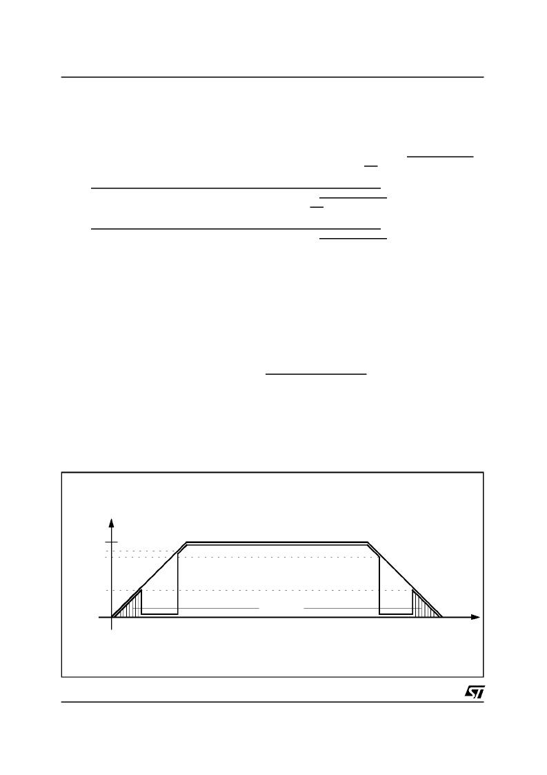
The voltageregulator also providesa reset signal POR at power up and power down to guarantee a well
defined state of the deviceat undervoltageconditions(see Fig. 1).
POR activatesthe reset pull down transistor performing a complete chip reset. In the same way a reset
POWERSUPPLY
(continued)
undefined
VCC
POR
5V
VReset OFF
Reset ON
V
t
Reset UD
V
Figure 1. Powerup/down characteristics
L9942
6/21
相關(guān)PDF資料 |
PDF描述 |
|---|---|
| L9997ND | Dual Half Bridge Driver(雙半橋驅(qū)動器) |
| LA070URD31LI350 | Square Body Semiconductor Fuses |
| LA100P80-1TI | LA100P Semiconductor Fuses |
| LA100P80-4TI | LA100P Semiconductor Fuses |
| LA120X4-1 | LA120X Semiconductor Fuses |
相關(guān)代理商/技術(shù)參數(shù) |
參數(shù)描述 |
|---|---|
| L9942XP1 | 功能描述:低壓差穩(wěn)壓器 - LDO Integrated Stepper Bipolar Motor Driver RoHS:否 制造商:Texas Instruments 最大輸入電壓:36 V 輸出電壓:1.4 V to 20.5 V 回動電壓(最大值):307 mV 輸出電流:1 A 負(fù)載調(diào)節(jié):0.3 % 輸出端數(shù)量: 輸出類型:Fixed 最大工作溫度:+ 125 C 安裝風(fēng)格:SMD/SMT 封裝 / 箱體:VQFN-20 |
| L9942XP1TR | 功能描述:馬達/運動/點火控制器和驅(qū)動器 Integrated Stepper Bipolar Motor Driver RoHS:否 制造商:STMicroelectronics 產(chǎn)品:Stepper Motor Controllers / Drivers 類型:2 Phase Stepper Motor Driver 工作電源電壓:8 V to 45 V 電源電流:0.5 mA 工作溫度:- 25 C to + 125 C 安裝風(fēng)格:SMD/SMT 封裝 / 箱體:HTSSOP-28 封裝:Tube |
| L9946 | 制造商:未知廠家 制造商全稱:未知廠家 功能描述:DC Motor Controller/Driver |
| L9947 | 制造商:STMICROELECTRONICS 制造商全稱:STMicroelectronics 功能描述:QUAD HALF-BRIDGE AND SINGLE HIGH-SIDE DRIVER |
| L9947L | 制造商:STMicroelectronics 功能描述: |
發(fā)布緊急采購,3分鐘左右您將得到回復(fù)。