- 您現(xiàn)在的位置:買賣IC網(wǎng) > PDF目錄1915 > DS2483Q+T (Maxim Integrated Products)IC I2C TO 1WIRE BRIDGE 8TDFN PDF資料下載
參數(shù)資料
| 型號: | DS2483Q+T |
| 廠商: | Maxim Integrated Products |
| 文件頁數(shù): | 12/29頁 |
| 文件大小: | 0K |
| 描述: | IC I2C TO 1WIRE BRIDGE 8TDFN |
| 產(chǎn)品培訓模塊: | Obsolescence Mitigation Program |
| 標準包裝: | 2,500 |
| 系列: | * |
第1頁第2頁第3頁第4頁第5頁第6頁第7頁第8頁第9頁第10頁第11頁當前第12頁第13頁第14頁第15頁第16頁第17頁第18頁第19頁第20頁第21頁第22頁第23頁第24頁第25頁第26頁第27頁第28頁第29頁
2
Maxim Integrated
DS2483
Single-Channel 1-Wire Master
with Adjustable Timing and Sleep Mode
Voltage Range on Any Pin Relative to Ground.......-0.5V to +6V
Maximum Current into Any Pin...........................................20mA
Continuous Power Dissipation (TA = +70NC)
SOT23 (derate 8.7mW/NC above +70NC).................695.7mW
TDFN (derate 16.7mW/NC above +70NC)...............1333.3mW
Operating Temperature Range.......................... -40NC to +85NC
Junction Temperature .....................................................+150NC
Storage Temperature Range............................ -55NC to +125NC
Lead Temperature (soldering, 10s) ................................+300NC
Soldering Temperature (reflow) ......................................+260NC
ABSOLUTE MAXIMUM RATINGS
Stresses beyond those listed under “Absolute Maximum Ratings” may cause permanent damage to the device. These are stress ratings only, and functional opera-
tion of the device at these or any other conditions beyond those indicated in the operational sections of the specifications is not implied. Exposure to absolute
maximum rating conditions for extended periods may affect device reliability.
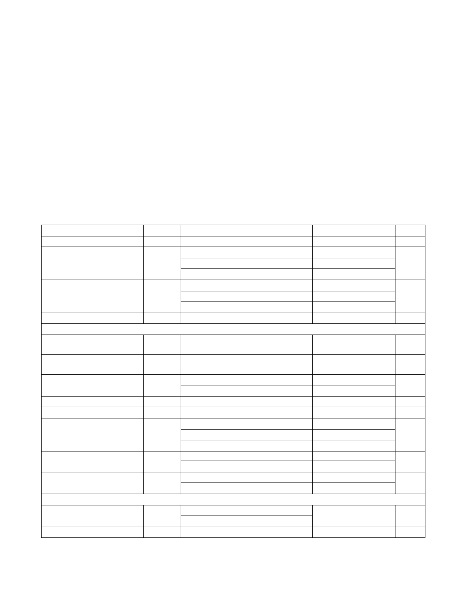
ELECTRICAL CHARACTERISTICS
(TA = -40NC to +85NC, unless otherwise noted.) (Note 1)
PARAMETER
SYMBOL
CONDITIONS
MIN
TYP
MAX
UNITS
Supply Voltage
VCC
2.97
5.25
V
I2C Voltage (Note 2)
VCI2C
1.8V
1.71
1.8
1.89
V
3.3V
2.97
3.3
3.63
5V
4.5
5.0
5.25
Supply Current
ICC
No communication, VCC = full range
300
F
A
Sleep mode, VCC = 5.25V
4
Sleep mode, VCC = 3.6V
3.0
Power-On-Reset Trip Point
VPOR
VCC = full range
1.0
1.5
V
IO PIN: GENERAL DATA
1-Wire Input High Voltage
VIH1
VCC = full range
0.6 O
VCC
V
1-Wire Input Low Voltage
VIL1
VCC = full range
0.2 O
VCC
V
1-Wire Weak Pullup Resistor
RWPU
Low range
375
500
815
I
High range
700
1000
1375
1-Wire Output Low Voltage
VOL1
IOL = 8mA sink current
0.2
V
Active Pullup On-Threshold
VIAPO
VCC = full range
0.6
0.95
1.2
V
Active Pullup On-Time (Note 3)
tAPU
1-Wire time slot
See APU bit description
F
s
1-Wire reset standard speed
2.375
2.5
2.625
1-Wire reset overdrive speed
0.475
0.5
0.525
Active Pullup Impedance
RAPU
VCC = 3.0V, 4mA load
60
I
VCC = 4.5V, 4mA load
40
1-Wire Output Fall Time (Note 4)
tF1
Standard, 10pF < CLOAD < 400pF
0.25
1
F
s
Overdrive, 10pF < CLOAD < 400pF
0.05
0.2
IO PIN: 1-Wire TIMING (Note 5)
Reset Low Time
tRSTL
Standard
-5%
See
Table 7
+5%
F
s
Overdrive
Reset High Time
tRSTH
Standard and overdrive
Equal to tRSTL
F
s
相關PDF資料 |
PDF描述 |
|---|---|
| DS2490Y | IC BRIDGE CLIP USB TO 1-W 24SOIC |
| DS26303LN-75+A3 | IC LIU E1/T1/J1 3.3V 144-ELQFP |
| DS26324GNA2+ | IC INTERFACE LINE 16CH 256-CSBGA |
| DS26334GN+ | IC INTERFACE LINE 16CH 256-CSBGA |
| DS26401N+ | IC OCTAL FRAMER T1/E1/J1 256-BGA |
相關代理商/技術參數(shù) |
參數(shù)描述 |
|---|---|
| DS2483R+T | 功能描述:I2C 接口集成電路 Single-Channel 1-Wire Master RoHS:否 制造商:NXP Semiconductors 電源電壓-最大:5.5 V 電源電壓-最小:2.3 V 最大工作頻率:400 KHz 最大工作溫度:+ 85 C 封裝 / 箱體:TSSOP-16 |
| DS2483R+U | 功能描述:接口 - 專用 SINGLE-CH 1-WIRE MASTER RoHS:否 制造商:Texas Instruments 產(chǎn)品類型:1080p60 Image Sensor Receiver 工作電源電壓:1.8 V 電源電流:89 mA 最大功率耗散: 最大工作溫度:+ 85 C 安裝風格:SMD/SMT 封裝 / 箱體:BGA-59 |
| DS2484Q+T | 制造商:Maxim Integrated Products 功能描述: |
| DS2484R+T | 制造商:Maxim Integrated Products 功能描述: |
| DS2490 | 制造商:MAXIM 制造商全稱:Maxim Integrated Products 功能描述:USB to 1-Wire Bridge Chip |
發(fā)布緊急采購,3分鐘左右您將得到回復。