- 您現(xiàn)在的位置:買賣IC網(wǎng) > PDF目錄97865 > DS1963L-F5 (DALLAS SEMICONDUCTOR) SPECIALTY MEMORY CIRCUIT, MEDB2 PDF資料下載
參數(shù)資料
| 型號: | DS1963L-F5 |
| 廠商: | DALLAS SEMICONDUCTOR |
| 元件分類: | Memory IC:Other |
| 英文描述: | SPECIALTY MEMORY CIRCUIT, MEDB2 |
| 封裝: | MICROCAN-2 |
| 文件頁數(shù): | 11/24頁 |
| 文件大小: | 482K |
| 代理商: | DS1963L-F5 |
DS1963L
19 of 24
1-WIRE SIGNALING
The DS1963L requires strict protocols to ensure data integrity. The protocol consists of four types of
signaling on one line: Reset Sequence with Reset Pulse and Presence Pulse, Write 0, Write 1 and Read
Data. All these signals except presence pulse are initiated by the bus master. The DS1963L can
communicate at two different speeds, regular speed and Overdrive speed. If not explicitly set into the
Overdrive mode, the DS1963L will communicate at regular speed. While in Overdrive mode the fast
timing applies to all waveforms.
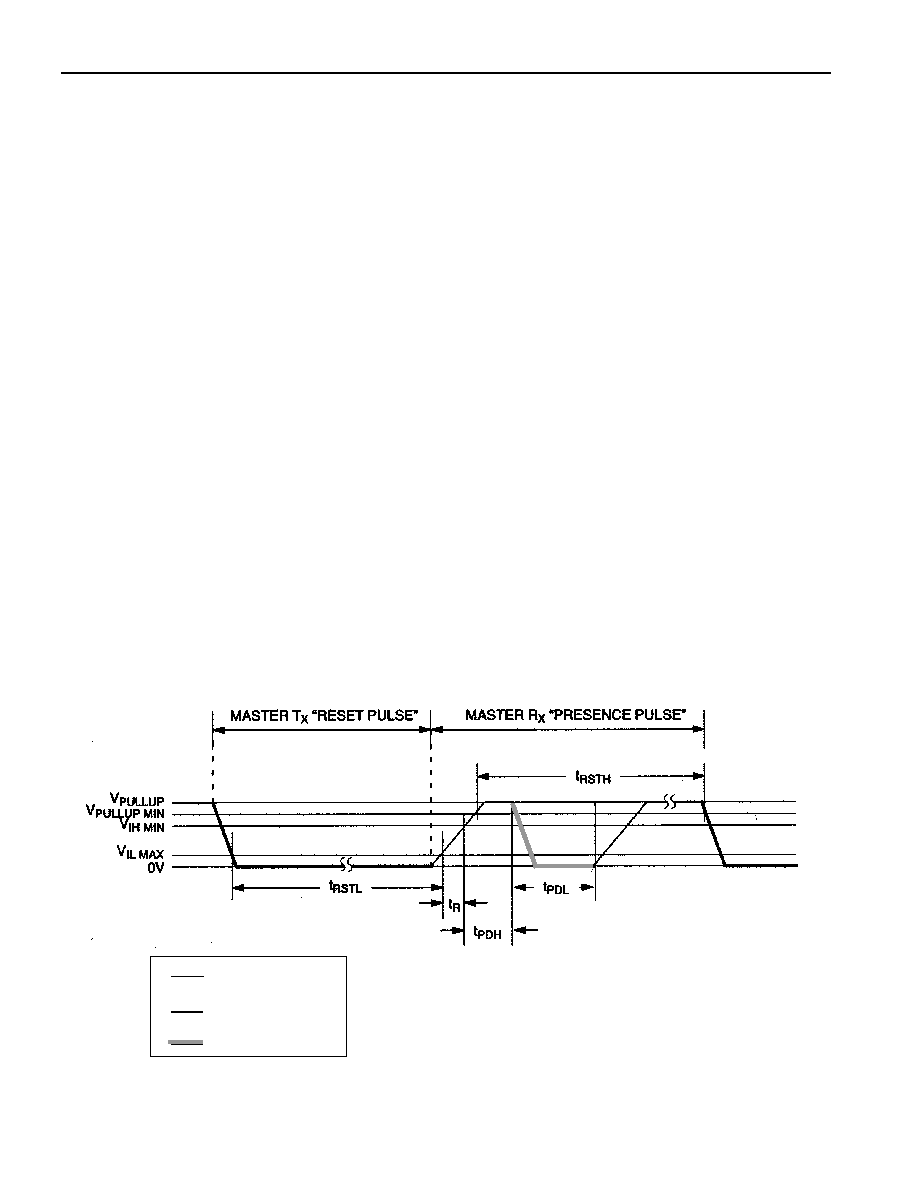
The initialization sequence required to begin any communication with the DS1963L is shown in Figure
10. A reset pulse followed by a presence pulse indicates the DS1963L is ready to send or receive data
given the correct ROM command and memory function command. The bus master transmits (TX) a reset
pulse (t RSTL , minimum 480
s at regular speed, 48 s at Overdrive speed). The bus master then releases
the line and goes into receive mode (RX). The 1-Wire bus is pulled to a high state via the pullup resistor.
After detecting the rising edge on the data pin, the DS1963L waits (t PDH , 15-60
s at regular speed, 2-6
s at Overdrive speed) and then transmits the presence pulse (t
PDL , 60-240
s at regular speed, 8-24 s at
Overdrive speed).
A reset pulse of 480
s or longer will exit the Overdrive mode returning the device to regular speed. If
the DS1963L is in Overdrive mode and the reset pulse is no longer than 80
s the device will remain in
Overdrive mode.
Read/Write Time Slots
The definitions of write and read time slots are illustrated in Figure 11. All time slots are initiated by the
master driving the data line low. The falling edge of the data line synchronizes the DS1963L to the master
by triggering a delay circuit in the DS1963L. During write time slots, the delay circuit determines when
the DS1963L will sample the data line. For a read data time slot, if a “0” is to be transmitted, the delay
circuit determines how long the DS1963L will hold the data line low overriding the 1 generated by the
master. If the data bit is a “1”, the device will leave the read data time slot unchanged.
INITIALIZATION PROCEDURE “RESET AND PRESENCE PLUSES” Figure 10
Regular Speed
Overdrive Speed
480
s ≤ t
RSTL < ∞ *
48
s ≤ t
RSTL < 80 s
480
s ≤ t
RSTH < ∞ **
48
s ≤ t
RSTH < ∞ **
15
s ≤ t
PDH < 60 s2 s ≤ tPDH < 6 s
60
s ≤ t
PDL < 240 s
8
s ≤ t
PDL < 24 s
*IN ORDER NOT TO MASK INTERRUPT SIGNALS BY OTHER DEVICES ON THE 1-WIRE BUS, tRSTL + tR SHOULD
ALWAYS BE LESS THAN 960
s
**INCLUDES RECOVERY TIME
RESISTOR
MASTER
DS1963L
相關(guān)PDF資料 |
PDF描述 |
|---|---|
| DS1963S | SPECIALTY MEMORY CIRCUIT, MEDB2 |
| DS1985-F3 | 2K X 8 EEPROM 3V, RDB2 |
| DS1986-F3 | 64K X 1 OTPROM, MEDB2 |
| DS1986-F5 | 64K X 1 OTPROM, MADB2 |
| DS1991L-F5 | SPECIALTY MEMORY CIRCUIT, MEDB2 |
相關(guān)代理商/技術(shù)參數(shù) |
參數(shù)描述 |
|---|---|
| DS1963L-F5+ | 功能描述:iButton RoHS:否 存儲類型:SRAM 存儲容量:512 B 組織: 工作電源電壓:3 V to 5.25 V 接口類型:1-Wire 最大工作溫度:+ 85 C 尺寸:17.35 mm x 5.89 mm 封裝 / 箱體:F5 MicroCan 制造商:Maxim Integrated |
| DS1963L-F5+W | 功能描述:iButton RoHS:否 存儲類型:SRAM 存儲容量:512 B 組織: 工作電源電壓:3 V to 5.25 V 接口類型:1-Wire 最大工作溫度:+ 85 C 尺寸:17.35 mm x 5.89 mm 封裝 / 箱體:F5 MicroCan 制造商:Maxim Integrated |
| DS1963R-F5+ | 制造商:Maxim Integrated Products 功能描述:- Rail/Tube |
| DS1963S | 制造商:DALLAS 制造商全稱:Dallas Semiconductor 功能描述:SHA iButton |
| DS1963S+F5 | 制造商:Maxim Integrated Products 功能描述:SHA IBTN 8SOIC - Rail/Tube |
發(fā)布緊急采購,3分鐘左右您將得到回復(fù)。