- 您現(xiàn)在的位置:買(mǎi)賣(mài)IC網(wǎng) > PDF目錄373980 > ADE7169ASTZF16 (ANALOG DEVICES INC) Single-Phase Energy Measurement IC with 8052 MCU, RTC and LCD driver PDF資料下載
參數(shù)資料
| 型號(hào): | ADE7169ASTZF16 |
| 廠商: | ANALOG DEVICES INC |
| 元件分類: | 模擬信號(hào)調(diào)理 |
| 英文描述: | Single-Phase Energy Measurement IC with 8052 MCU, RTC and LCD driver |
| 中文描述: | SPECIALTY ANALOG CIRCUIT, QCC64 |
| 封裝: | 9 X 9 MM, ROHS COMPLIANT, MO-22-VMMD-4, LFCSP-64 |
| 文件頁(yè)數(shù): | 58/140頁(yè) |
| 文件大?。?/td> | 1359K |
| 代理商: | ADE7169ASTZF16 |
第1頁(yè)第2頁(yè)第3頁(yè)第4頁(yè)第5頁(yè)第6頁(yè)第7頁(yè)第8頁(yè)第9頁(yè)第10頁(yè)第11頁(yè)第12頁(yè)第13頁(yè)第14頁(yè)第15頁(yè)第16頁(yè)第17頁(yè)第18頁(yè)第19頁(yè)第20頁(yè)第21頁(yè)第22頁(yè)第23頁(yè)第24頁(yè)第25頁(yè)第26頁(yè)第27頁(yè)第28頁(yè)第29頁(yè)第30頁(yè)第31頁(yè)第32頁(yè)第33頁(yè)第34頁(yè)第35頁(yè)第36頁(yè)第37頁(yè)第38頁(yè)第39頁(yè)第40頁(yè)第41頁(yè)第42頁(yè)第43頁(yè)第44頁(yè)第45頁(yè)第46頁(yè)第47頁(yè)第48頁(yè)第49頁(yè)第50頁(yè)第51頁(yè)第52頁(yè)第53頁(yè)第54頁(yè)第55頁(yè)第56頁(yè)第57頁(yè)當(dāng)前第58頁(yè)第59頁(yè)第60頁(yè)第61頁(yè)第62頁(yè)第63頁(yè)第64頁(yè)第65頁(yè)第66頁(yè)第67頁(yè)第68頁(yè)第69頁(yè)第70頁(yè)第71頁(yè)第72頁(yè)第73頁(yè)第74頁(yè)第75頁(yè)第76頁(yè)第77頁(yè)第78頁(yè)第79頁(yè)第80頁(yè)第81頁(yè)第82頁(yè)第83頁(yè)第84頁(yè)第85頁(yè)第86頁(yè)第87頁(yè)第88頁(yè)第89頁(yè)第90頁(yè)第91頁(yè)第92頁(yè)第93頁(yè)第94頁(yè)第95頁(yè)第96頁(yè)第97頁(yè)第98頁(yè)第99頁(yè)第100頁(yè)第101頁(yè)第102頁(yè)第103頁(yè)第104頁(yè)第105頁(yè)第106頁(yè)第107頁(yè)第108頁(yè)第109頁(yè)第110頁(yè)第111頁(yè)第112頁(yè)第113頁(yè)第114頁(yè)第115頁(yè)第116頁(yè)第117頁(yè)第118頁(yè)第119頁(yè)第120頁(yè)第121頁(yè)第122頁(yè)第123頁(yè)第124頁(yè)第125頁(yè)第126頁(yè)第127頁(yè)第128頁(yè)第129頁(yè)第130頁(yè)第131頁(yè)第132頁(yè)第133頁(yè)第134頁(yè)第135頁(yè)第136頁(yè)第137頁(yè)第138頁(yè)第139頁(yè)第140頁(yè)
ADE7169F16
Preliminary Technical Data
(default), the VARSIGN flag in the Interrupt Status Register 1
SFR (MIRQSTL, 0xDC) will be set when a transition from
positive to negative reactive power has occurred.
Rev. PrD | Page 58 of 140
When VARSIGN in the ACCMODE register (0x0F) is set, the
VARSIGN flag in the Interrupt Status Register 1 SFR
(MIRQSTL, 0xDC) will be set when a transition from negative
to positive reactive power has occurred.
Reactive power no-Load detection
The ADE7169F16 includes a no-load threshold feature on the
reactive energy that eliminates any creep effects in the meter.
The ADE7169F16 accomplishes this by not accumulating
reactive energy if the multiplier output is below the no-load
threshold. When the reactive power is below the no-load
threshold, the RNOLOAD flag in the Interrupt Status Register 1
SFR (MIRQSTL, 0xDC) is set. If the RNOLOAD bit is set in the
Interrupt Enable Register 1 SFR (MIRQENL, 0xD9), the 8052
core has a pending ADE interrupt. The ADE interrupt stays
active until the RNOLOAD status bit is cleared—see Energy
measurement interrupts section.
The No-load threshold level is selectable by setting bits
RNOLOAD in the NLMODE register (0x0E). Setting these bits
to 0b00 disable the no-load detection and setting them to 0b01,
0b10 or 0b11 set the no-load detection threshold to 0.015%,
0.0075% and 0.0037% of the full-scale output frequency of the
multiplier respectively.
VARGAIN[11:0]
VARDIV[7:0]
LPF2
CURRENT
CHANNEL
VOLTAGE
CHANNEL
O
TIME (nT)
5
CLKIN
T
REACTIVE POWER
SIGNAL
+
+
VARHR[23:0]
OUTPUTS FROM THE LPF2 ARE
ACCUMULATED (INTEGRATED) IN
THE INTERNAL REACTIVE ENERGY REGISTER
UPPER 24 BITS ARE
ACCESSIBLE THROUGH
VARHR[23:0] REGISTER
23
0
48
0
WAVEFORM
REGISTER
VALUES
%
VAROS[15:0]
2
6
sgn
2
5
2
-6
2
-7
2
-8
+
+
FORWAVEF0RM
SAMPLING
HPF
90° PHASE
SHIFTING FILTER
Π
2
PHCAL[7:0]
TO
DIGITALTO FREQUENCY
CONVERTER
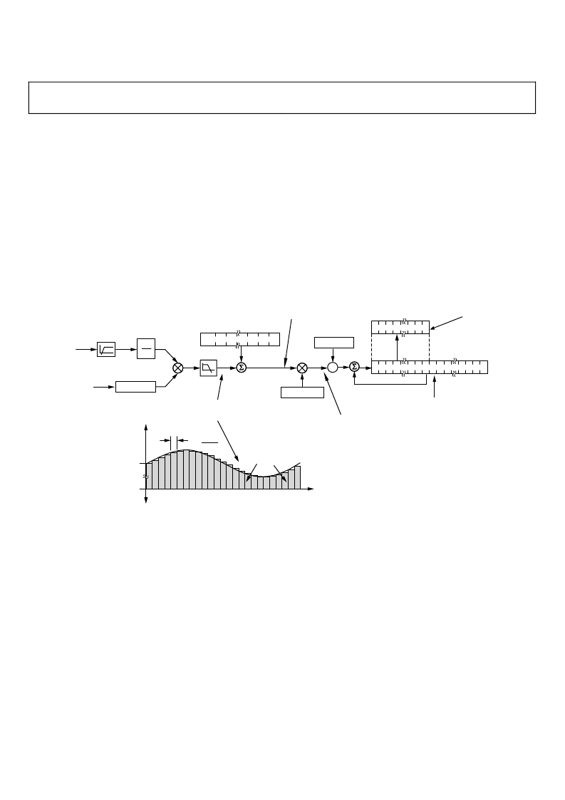
Figure 45. ADE7169F16 Reactive Energy Calculation
Reactive Energy Calculation
As for active energy, the ADE7169F16 achieves the integration
of the reactive power signal by continuously accumulating the
reactive power signal in an internal non-readable 49-bit energy
register. The reactive energy register (VARHR[23:0]) represents
the upper 24 bits of this internal register.
The discrete time sample period (
T
) for the accumulation
register in the ADE7169F16 is 1.22μs (5/MCLK). As well as
calculating the energy, this integration removes any sinusoidal
components that might be in the active power signal. Figure 45
shows this discrete time integration or accumulation. The
reactive power signal in the waveform register is continuously
added to the internal reactive energy register.
The reactive Energy accumulation depends on the setting of the
SAVARM and ABSVARM bits in the ACCMODE register
(0x0F). When both bits are cleared, the addition is signed and
therefore negative energy is subtracted from the reactive energy
contents. When both bits are set, the ADE7169F16 is set to be
in the more restrictive mode, the Absolute Accumulation mode.
When SAVARM bit in the ACCMODE register (0x0F) is set,
the reactive power is accumulated depending on the sign of the
active power. When active power is positive, the reactive power
is added as it is to the reactive energy register. When active
power is negative, the reactive power is subtracted to the
reactive energy accumulator – see VAR anti-tamper
accumulation mode.
When ABSVARM bit in the ACCMODE register (0x0F) is set,
the absolute reactive power is used for the reactive energy
accumulation—see the VAR absolute accumulation mode
section.
The output of the multiplier is divided by VARDIV. If the value
in the VARDIV register is equal to 0, then the internal reactive
相關(guān)PDF資料 |
PDF描述 |
|---|---|
| ADE7169ASTZF16-RL | Single-Phase Energy Measurement IC with 8052 MCU, RTC and LCD driver |
| ADE7169F16 | Single-Phase Energy Measurement IC with 8052 MCU, RTC and LCD driver |
| ADE7751 | Energy Metering IC with On-Chip Fault Detection |
| ADE7751AAN-REF | Energy Metering IC with On-Chip Fault Detection |
| ADE7751AN | Energy Metering IC with On-Chip Fault Detection |
相關(guān)代理商/技術(shù)參數(shù) |
參數(shù)描述 |
|---|---|
| ADE7169ASTZF16-RL | 功能描述:IC ENERGY METER 1PHASE 64LQFP RoHS:是 類別:集成電路 (IC) >> PMIC - 能量測(cè)量 系列:- 產(chǎn)品培訓(xùn)模塊:Lead (SnPb) Finish for COTS Obsolescence Mitigation Program 標(biāo)準(zhǔn)包裝:2,500 系列:* |
| ADE7169F16 | 制造商:AD 制造商全稱:Analog Devices 功能描述:Single-Phase Energy Measurement IC with 8052 MCU, RTC and LCD driver |
| ADE75 | 制造商:AD 制造商全稱:Analog Devices 功能描述:Single-Phase Energy Measurement IC with 8052 MCU, RTC and LCD driver |
| ADE7518ASTZF16 | 功能描述:IC ENERGY METER MCU 16K 64LQFP RoHS:是 類別:集成電路 (IC) >> PMIC - 能量測(cè)量 系列:- 產(chǎn)品培訓(xùn)模塊:Lead (SnPb) Finish for COTS Obsolescence Mitigation Program 標(biāo)準(zhǔn)包裝:2,500 系列:* |
| ADE7518ASTZF16-RL | 功能描述:IC ENERGY METER MCU 16K 64LQFP RoHS:是 類別:集成電路 (IC) >> PMIC - 能量測(cè)量 系列:- 產(chǎn)品培訓(xùn)模塊:Lead (SnPb) Finish for COTS Obsolescence Mitigation Program 標(biāo)準(zhǔn)包裝:2,500 系列:* |
發(fā)布緊急采購(gòu),3分鐘左右您將得到回復(fù)。