- 您現(xiàn)在的位置:買賣IC網(wǎng) > PDF目錄373979 > ADE7169ACPF16 (ANALOG DEVICES INC) Single-Phase Energy Measurement IC with 8052 MCU, RTC and LCD driver PDF資料下載
參數(shù)資料
| 型號: | ADE7169ACPF16 |
| 廠商: | ANALOG DEVICES INC |
| 元件分類: | 模擬信號調理 |
| 英文描述: | Single-Phase Energy Measurement IC with 8052 MCU, RTC and LCD driver |
| 中文描述: | ANALOG CIRCUIT, QCC64 |
| 封裝: | 9 X 9MM, MO-220VMMD, LFCSP-64 |
| 文件頁數(shù): | 79/140頁 |
| 文件大小: | 1359K |
| 代理商: | ADE7169ACPF16 |
第1頁第2頁第3頁第4頁第5頁第6頁第7頁第8頁第9頁第10頁第11頁第12頁第13頁第14頁第15頁第16頁第17頁第18頁第19頁第20頁第21頁第22頁第23頁第24頁第25頁第26頁第27頁第28頁第29頁第30頁第31頁第32頁第33頁第34頁第35頁第36頁第37頁第38頁第39頁第40頁第41頁第42頁第43頁第44頁第45頁第46頁第47頁第48頁第49頁第50頁第51頁第52頁第53頁第54頁第55頁第56頁第57頁第58頁第59頁第60頁第61頁第62頁第63頁第64頁第65頁第66頁第67頁第68頁第69頁第70頁第71頁第72頁第73頁第74頁第75頁第76頁第77頁第78頁當前第79頁第80頁第81頁第82頁第83頁第84頁第85頁第86頁第87頁第88頁第89頁第90頁第91頁第92頁第93頁第94頁第95頁第96頁第97頁第98頁第99頁第100頁第101頁第102頁第103頁第104頁第105頁第106頁第107頁第108頁第109頁第110頁第111頁第112頁第113頁第114頁第115頁第116頁第117頁第118頁第119頁第120頁第121頁第122頁第123頁第124頁第125頁第126頁第127頁第128頁第129頁第130頁第131頁第132頁第133頁第134頁第135頁第136頁第137頁第138頁第139頁第140頁
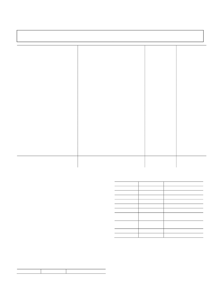
Preliminary Technical Data
ADE7169F16
Mnemonic
JMP @A+DPTR
Rev. PrD | Page 79 of 140
Description
Jump indirect relative to DPTR
Bytes
1
Cycles
3
RET
RETI
ACALL addr11
AJMP addr11
SJMP rel
JC rel
JNC rel
JZ rel
JNZ rel
DJNZ Rn,rel
LJMP
LCALL addr16
JB bit,rel
JNB bit,rel
JBC bit,rel
CJNE A,dir,rel
CJNE A,#data,rel
CJNE Rn,#data,rel
CJNE @Ri,#data,rel
DJNZ dir,rel
Return from subroutine
Return from interrupt
Absolute jump to subroutine
Absolute jump unconditional
Short jump (relative address)
Jump on carry equal to 1
Jump on carry equal to 0
Jump on accumulator =0
Jump on accumulator not equal to 0
Decrement register,JNZ relative
Long jump unconditional
Long jump to subroutine
Jump on direct bit =1
Jump on direct bit =0
Jump on direct bit =1 and clear
Compare A,direct JNE relative
Compare A,immediate JNE relative
Compare register,immediate JNE relative
Compare indirect,immediate JNE relative
Decrement direct byte,JNZ relative
1
1
2
2
2
2
2
2
2
2
3
3
3
3
3
3
3
3
3
3
4
4
3
3
3
3
3
3
3
3
4
4
4
4
4
4
4
4
4
4
Miscellaneous
NOP
No operation
1
1
READ-MODIFY-WRITE INSTRUCTIONS
Some 8051 instructions read the latch while others read the pin.
The state of the pin is read for instructions that input a port bit.
Instructions that read the latch rather than the pins are the ones
that read a value, possibly change it, and rewrite it to the latch.
Since these instructions involve modifying the port, it is
assumed that the pins being modified are outputs, so the output
state of the pin is read from the latch. This prevents a possible
misinterpretation of the voltage level of a pin. For example, if a
port pin is used to drive the base of a transistor, a 1 is written to
the bit, to turn the transistor on. If the CPU reads the same port
bit at the pin rather than the latch, it reads the base voltage of
the transistor and interprets it as Logic 0. Reading the latch
rather than the pin returns the correct value of 1.
The instructions that read the latch rather than the pins are
called read-modify-write instructions, and are listed in Table
61. When the destination operand is a port or a port bit, these
instructions read the latch rather than the pin.
Table 61. Read-Modify-Write Instructions
Instruction
Example
Description
ANL
ORL
XRL
JBC
CPL
INC
DEC
DJNZ
ANL P0, A
ORL P1, A
XRL P2, A
JBC P1.1, LABEL
CPL P2.0
INC P2
DEC P2
DJNZ P0, LABEL
Logical AND
Logical OR
Logical EX-OR
Jump if Bit = 1 and clear bit
Complement bit
Increment
Decrement
Decrement and jump if not
zero
Move Carry to Bit Y of Port
X
Clear Bit Y of Port X
Set Bit Y of Port X
MOV PX.Y, C
1
MOV P0.0,C
CLR PX.Y
1
SETB PX.Y
1
___________________________________________
CLR P0.0
SETB P0.0
1
These instructions read the port byte (all 8 bits), modify the addressed bit,
and write the new byte back to the latch.
INSTRUCTIONS THAT AFFECT FLAGS
Many instructions explicitly modify the Carry bit such as the
MOV C, bit and CLR C instructions. Other instructions that
affect status flags are listed in this section.
相關PDF資料 |
PDF描述 |
|---|---|
| ADE7169ACPF16-RL | Single-Phase Energy Measurement IC with 8052 MCU, RTC and LCD driver |
| ADE7169ACPZF16 | Single-Phase Energy Measurement IC with 8052 MCU, RTC and LCD driver |
| ADE7169ACPZF16-RL | Single-Phase Energy Measurement IC with 8052 MCU, RTC and LCD driver |
| ADE7169ASTF16 | Single-Phase Energy Measurement IC with 8052 MCU, RTC and LCD driver |
| ADE7169ASTF16-RL | Single-Phase Energy Measurement IC with 8052 MCU, RTC and LCD driver |
相關代理商/技術參數(shù) |
參數(shù)描述 |
|---|---|
| ADE7169ACPF16-RL | 制造商:AD 制造商全稱:Analog Devices 功能描述:Single-Phase Energy Measurement IC with 8052 MCU, RTC and LCD driver |
| ADE7169ACPZF16 | 制造商:AD 制造商全稱:Analog Devices 功能描述:Single-Phase Energy Measurement IC with 8052 MCU, RTC, and LCD Driver |
| ADE7169ACPZF161 | 制造商:AD 制造商全稱:Analog Devices 功能描述:Single-Phase Energy Measurement IC with 8052 MCU, RTC and LCD driver |
| ADE7169ACPZF16-RL | 制造商:AD 制造商全稱:Analog Devices 功能描述:Single-Phase Energy Measurement IC with 8052 MCU, RTC, and LCD Driver |
| ADE7169ACPZF16-RL1 | 制造商:AD 制造商全稱:Analog Devices 功能描述:Single-Phase Energy Measurement IC with 8052 MCU, RTC and LCD driver |
發(fā)布緊急采購,3分鐘左右您將得到回復。