- 您現(xiàn)在的位置:買(mǎi)賣(mài)IC網(wǎng) > PDF目錄375249 > AD9865BCP (ANALOG DEVICES INC) Broadband Modem Mixed-Signal Front End PDF資料下載
參數(shù)資料
| 型號(hào): | AD9865BCP |
| 廠商: | ANALOG DEVICES INC |
| 元件分類(lèi): | 通信及網(wǎng)絡(luò) |
| 英文描述: | Broadband Modem Mixed-Signal Front End |
| 中文描述: | SPECIALTY TELECOM CIRCUIT, QCC64 |
| 封裝: | MO-220-VMMD, LFCSP-64 |
| 文件頁(yè)數(shù): | 30/48頁(yè) |
| 文件大?。?/td> | 1672K |
| 代理商: | AD9865BCP |
第1頁(yè)第2頁(yè)第3頁(yè)第4頁(yè)第5頁(yè)第6頁(yè)第7頁(yè)第8頁(yè)第9頁(yè)第10頁(yè)第11頁(yè)第12頁(yè)第13頁(yè)第14頁(yè)第15頁(yè)第16頁(yè)第17頁(yè)第18頁(yè)第19頁(yè)第20頁(yè)第21頁(yè)第22頁(yè)第23頁(yè)第24頁(yè)第25頁(yè)第26頁(yè)第27頁(yè)第28頁(yè)第29頁(yè)當(dāng)前第30頁(yè)第31頁(yè)第32頁(yè)第33頁(yè)第34頁(yè)第35頁(yè)第36頁(yè)第37頁(yè)第38頁(yè)第39頁(yè)第40頁(yè)第41頁(yè)第42頁(yè)第43頁(yè)第44頁(yè)第45頁(yè)第46頁(yè)第47頁(yè)第48頁(yè)
AD9865
Table 19. SPI Registers for TxDAC and IAMP
Address (Hex)
Bit
0x0E
(0)
0x10
(7)
(6:4) Secondary path first stage gain of 0
to 4 with = 1
(3)
Not used
(2:0) Primary path NMOS gain of 0 to 4
with = 1
0x11
(7)
Don’t care
(6:4) Secondary path second stage gain of
0 to 1.5 with = 0.25
(3)
Not used
(2:0) Secondary path third stage gain of 0
to 5 with = 1
0x12
(6:4) IOFF2, secondary path standing
current
(2:0) IOFF1, primary path standing current
Rev. A | Page 30 of 48
Description
TxDAC output
Enable current mirror gain settings
Tx PROGRAMMABLE GAIN CONTROL
TxPGA functionality is also available to set the peak output
current from the TxDAC or IAMP. The TxDAC and IAMP are
digitally programmable via the PGA[5:0] port or SPI over a 0 dB
to 7.5 dB and 0 dB to 19.5 dB range, respectively, in 0.5 dB
increments.
The TxPGA can be considered as two cascaded attenuators with
the TxDAC providing 7.5 dB range in 0.5 dB increments, and
the IAMP providing 12 dB range in 6 dB increments. As a
result, the IAMP’s composite 19.5 dB span is valid only if
Register 0x10 remains at its default setting of 0x44. Modifying
this register setting corrupts the LUT and results in an invalid
gain mapping.
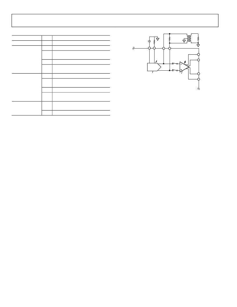
TxDAC OUTPUT OPERATION
The differential current output of the TxDAC is available at the
IOUTP+ and IOUTP pins and the IAMP should be disabled
by setting Bit 0 of Register 0x0E. Any load connected to these
pins must be ground referenced to provide a dc path for the
current sources. Figure 63 shows the outputs of the TxDAC
driving a doubly terminated 1:1 transformer with its center-tap
tied to ground. The peak-to-peak voltage, V p-p, across R
L
(and
IOUT+ to IOUT) is equal to 2 × I × (R
L
//R
S
). With I = 10 mA
and R
L
= R
S
= 50 , V p-p is equal to 0.5 V with 1 dBm of peak
power being delivered to R
L
and 1 dBm being dissipated in R
S
.
4
IOUTN–
IOUTN+
IOUTG–
IOUTG+
I
I
0 TO –7.5dB
0 TO –12dB
IAMP
R
R
R
SET
0.1
μ
F
R
S
1:1
R
L
TxDAC
Figure 63. TxDAC Output Directly via Center-Tap Transformer
The TxDAC is capable of delivering up to 10 dBm peak power
to a load, R
L
. To increase the peak power for a fixed standing
current, one must increase V p-p across IOUTP+ and IOUTP
by increasing one or more of the following parameters: R
S
, R
L
(if
possible), and/or the turns ratio, N, of transformer. For exam-
ple, the removal of R
S
and the use of a 2:1 impedance
ratio
transformer in the previous example results in 10 dBm of peak
power capabilities to the load. Note that increasing the power
output capabilities of the TxDAC reduces the distortion per-
formance due to the higher voltage swings seen at IOUTP+ and
IOUTP. See Figure 27 through Figure 38 for performance
plots on the TxDAC’s ac performance. Optimum distortion
performance can typically be achieved by:
Limiting the peak positive V
IOUTP+
and V
IOUTP
to 0.8 V to
avoid onset of TxDAC’s output compression. (TxDAC’s
voltage compliance is around 1.2 V.)
Limiting V p-p seen at IOUTP+ and IOUTP to less
than 1.6 V.
Applications demanding higher output voltage swings and
power drive capabilities can benefit from using the IAMP.
IAMP CURRENT-MODE OPERATION
The IAMP can be configured for the current-mode operation as
shown in Figure 64 for loads remaining relatively constant. In
this mode, the primary path mirrors should be used to deliver
the signal-dependent current to the load via a center-tapped
transformer, because it provides the best linearity performance.
Because the mirrors exhibit a high output impedance, they can
be easily back-terminated (if required).
For peak signal currents (IOUT
PK
up to 50 mA), only the
primary path mirror gain should be used for optimum
distortion performance and power efficiency. The primary
path’s gain should be set to 4, with the secondary path’s gain
stages set to 0 (Register 0x10 = 0x84). The TxDAC’s standing
current, I, can be set between 2.5 mA and 12.5 mA with the
IOUTP outputs left open. The IOUTN outputs should be
connected to the transformer, with the IOUTG (and IOUTP)
相關(guān)PDF資料 |
PDF描述 |
|---|---|
| AD9865BCPRL | Broadband Modem Mixed-Signal Front End |
| AD9865BCPZ1 | Broadband Modem Mixed-Signal Front End |
| AD9865BCPZRL1 | Broadband Modem Mixed-Signal Front End |
| AD9865CHIPS | Broadband Modem Mixed-Signal Front End |
| AD9887 | Dual Interface for Flat Panel Displays |
相關(guān)代理商/技術(shù)參數(shù) |
參數(shù)描述 |
|---|---|
| AD9865BCPRL | 制造商:Analog Devices 功能描述:Mixed Signal Front End 64-Pin LFCSP EP T/R |
| AD9865BCPZ | 功能描述:IC PROCESSOR FRONT END 64LFCSP RoHS:是 類(lèi)別:RF/IF 和 RFID >> RF 前端 (LNA + PA) 系列:- 產(chǎn)品培訓(xùn)模塊:Lead (SnPb) Finish for COTS Obsolescence Mitigation Program 標(biāo)準(zhǔn)包裝:250 系列:- RF 型:GPS 頻率:1575.42MHz 特點(diǎn):- 封裝/外殼:48-TQFP 裸露焊盤(pán) 供應(yīng)商設(shè)備封裝:48-TQFP 裸露焊盤(pán)(7x7) 包裝:托盤(pán) |
| AD9865BCPZ1 | 制造商:AD 制造商全稱(chēng):Analog Devices 功能描述:Broadband Modem Mixed-Signal Front End |
| AD9865BCPZRL | 功能描述:IC PROCESSOR FRONT END 64LFCSP RoHS:是 類(lèi)別:RF/IF 和 RFID >> RF 前端 (LNA + PA) 系列:- 產(chǎn)品培訓(xùn)模塊:Lead (SnPb) Finish for COTS Obsolescence Mitigation Program 標(biāo)準(zhǔn)包裝:250 系列:- RF 型:GPS 頻率:1575.42MHz 特點(diǎn):- 封裝/外殼:48-TQFP 裸露焊盤(pán) 供應(yīng)商設(shè)備封裝:48-TQFP 裸露焊盤(pán)(7x7) 包裝:托盤(pán) |
| AD9865BCPZRL1 | 制造商:AD 制造商全稱(chēng):Analog Devices 功能描述:Broadband Modem Mixed-Signal Front End |
發(fā)布緊急采購(gòu),3分鐘左右您將得到回復(fù)。