- 您現(xiàn)在的位置:買賣IC網(wǎng) > PDF目錄11674 > AD2S90APZ (Analog Devices Inc)IC R/D CONV 12BIT 20-PLCC PDF資料下載
參數(shù)資料
| 型號(hào): | AD2S90APZ |
| 廠商: | Analog Devices Inc |
| 文件頁(yè)數(shù): | 10/12頁(yè) |
| 文件大?。?/td> | 0K |
| 描述: | IC R/D CONV 12BIT 20-PLCC |
| 標(biāo)準(zhǔn)包裝: | 1 |
| 類型: | R/D 轉(zhuǎn)換器 |
| 輸入類型: | 并聯(lián) |
| 輸出類型: | 數(shù)字 |
| 接口: | 串行 |
| 電流 - 電源: | 10mA |
| 安裝類型: | 表面貼裝 |
| 封裝/外殼: | 20-LCC(J 形引線) |
| 供應(yīng)商設(shè)備封裝: | 20-PLCC(9x9) |
| 包裝: | 管件 |
| 產(chǎn)品目錄頁(yè)面: | 790 (CN2011-ZH PDF) |
AD2S90
REV. D
–7–
VELOCITY OUTPUT
The analog velocity output VEL is scaled to produce 150 rps/V
dc
± 15%. The sense is positive V dc for increasing angular
rotation. VEL can drive a maximum load combination of
10 k
and 30 pF. The internal velocity scaling is fixed.
POSITION CONTROL
The rotor movement of dc or ac motors used for servo control is
monitored at all times. Feedback transducers used for this pur-
pose detect either relative position in the case of an incremental
encoder or absolute position and velocity using a resolver. An
incremental encoder only measures change in position not
actual position.
Closed Loop Control Systems
The primary demand for a change in position must take into
account the magnitude of that change and the associated accel-
eration and velocity characteristics of the servo system. This is
necessary to avoid “hunting” due to over- or underdamping of
the control employed.
A position loop needs both actual and demand position infor-
mation. Algorithms consisting of proportional, integral and
derivative control (PID) may be implemented to control the
velocity profile.
A simplified position loop is shown in Figure 8.
POSITION
DEMAND
POSITION CONTROLLER
RE-
SOLVER
ACTUAL
POSITION
SERVO
MOTOR
AD2S90
SERVO
AMP
Figure 8. Position Loop
MOTION CONTROL PROCESSES
Advanced VLSI designs mean that silicon system blocks are now
available to achieve high performance motion control in servo
systems.
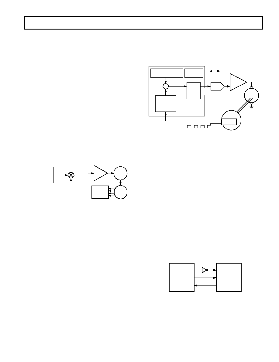
A digital position control system using the AD2S90 is shown in
Figure 9. In this system the task of determining the acceleration
and velocity characteristics is fulfilled by programming a trap-
ezoidal velocity profile via the I/O port.
As can be seen from Figure 9 encoder position feedback infor-
mation is used. This is a popular format and one which the
AD2S90 emulates thereby facilitating the replacement of encod-
ers with an AD2S90 and a resolver. However, major benefits
can be realized by adopting the resolver principle as opposed to
the incremental technique.
Incremental feedback based systems normally carry out a peri-
odic check between the position demanded by the controller
and the increment position count. This requires software and
hardware comparisons and battery backup in the case of power
failure. If there is a supply failure and the drive system moves,
unless all parts of the system are backed up, a reset to a known
datum point needs to take place. This can be extremely hazard-
ous in many applications. The AD2S90 gets round this problem
by supplying an absolute position serial data stream upon re-
quest, thus removing the need to reset to a known datum.
INCREMENTAL POSITION
+
–
RESOLVER
OPTIONAL
VELOCITY
FEEDBACK
HOST I/O
PORT
TO HOST PROCESSOR
ABSOLUTE
POSITION
HOST
INTERFACE
COMMAND POSITION
SEQUENCER (32-BIT)
POSITION
FEEDBACK
PROCESSOR
(32-BIT)
IN, A, B
AD2S90
DC
MOTOR
DAC
PORT
DIGITAL
PID
FILTER
(16-BIT)
8 – 12
DAC
POWER
AMP
Figure 9. Practical Implementation of the AD2S90
DSP Interfacing
The AD2S90 serial output is ideally suited for interfacing to
DSP configured microprocessors. Figures 10 to 13 illustrate
how to configure the AD2S90 for serial interfacing to the DSP.
ADSP-2105 Interfacing
Figure 10 shows the AD2S90 interfaced to an ADSP-2105. The
on-chip serial port of the ADSP-2105 is used in alternate fram-
ing receive mode with internal framing (internally inverted) and
internal serial clock generation (externally inverted) options
selected. In this mode the ADSP-2105 provides a
CS and a
serial clock to the AD2S90. The serial clock is inverted to pre-
vent timing errors as a result of both the AD2S90 and ADSP-
2105 clock data on the negative edge of SCLK. The first data
bit is void; 12 bits of significant data then follow on each con-
secutive negative edge of the clock. Data is clocked from the
AD2S90 into the data receive register of the ADSP-2105. This
is internally set to 13 bit (12 bits and one “dummy” bit) when
13 bits are received. The serial port automatically generates an
internal processor interrupt. This allows the ADSP-2105 to read
12 significant bits at once and continue processing.
The ADSP-2101, ADSP-2102, ADSP-2111 and 21msp50 can
all interface to the AD2S90 with similar interface circuitry.
SCLK
RFS
DR
SCLK
CS
DATA
ADSP-2105
AD2S90
NOTE:
ADDITIONAL PINS OMITTED FOR CLARITY
Figure 10. ADSP-2105/AD2S90 Serial Interface
相關(guān)PDF資料 |
PDF描述 |
|---|---|
| 226990-3 | CONN JACK BNC RT/A 50OHM PCB AU |
| AD598JRZ | IC LVDT SGNL COND OSC/REF 20SOIC |
| 221185-2 | CONN PLUG BNC 75 OHM DUAL CRIMP |
| AD698APZ | IC LVDT SIGNAL COND 28-PLCC |
| 221185-8 | CONN PLUG BNC 75 OHM DUAL CRIMP |
相關(guān)代理商/技術(shù)參數(shù) |
參數(shù)描述 |
|---|---|
| AD2S90APZ-MOOG | 制造商:Analog Devices 功能描述: |
| AD2S90APZ-RL7 | 功能描述:IC R/D CONV 12BIT 20-PLCC 制造商:analog devices inc. 系列:* 零件狀態(tài):在售 標(biāo)準(zhǔn)包裝:250 |
| AD2S90-EB | 制造商:Analog Devices 功能描述:EVALUATION BOARD - Bulk |
| AD2S93 | 制造商:AD 制造商全稱:Analog Devices 功能描述:Low Cost LVDT-to-Digital Converter |
| AD2S93AP | 制造商:AD 制造商全稱:Analog Devices 功能描述:Low Cost LVDT-to-Digital Converter |
發(fā)布緊急采購(gòu),3分鐘左右您將得到回復(fù)。