- 您現(xiàn)在的位置:買(mǎi)賣(mài)IC網(wǎng) > PDF目錄25049 > 0C585-002-XTD S-FSK PLC Modem PDF資料下載
參數(shù)資料
| 型號(hào): | 0C585-002-XTD |
| 英文描述: | S-FSK PLC Modem |
| 中文描述: | 第S - FSK信號(hào)的PLC調(diào)制解調(diào)器 |
| 文件頁(yè)數(shù): | 8/11頁(yè) |
| 文件大小: | 277K |
| 代理商: | 0C585-002-XTD |
AMIS-30600 LIN Transceiver
Data Sheet
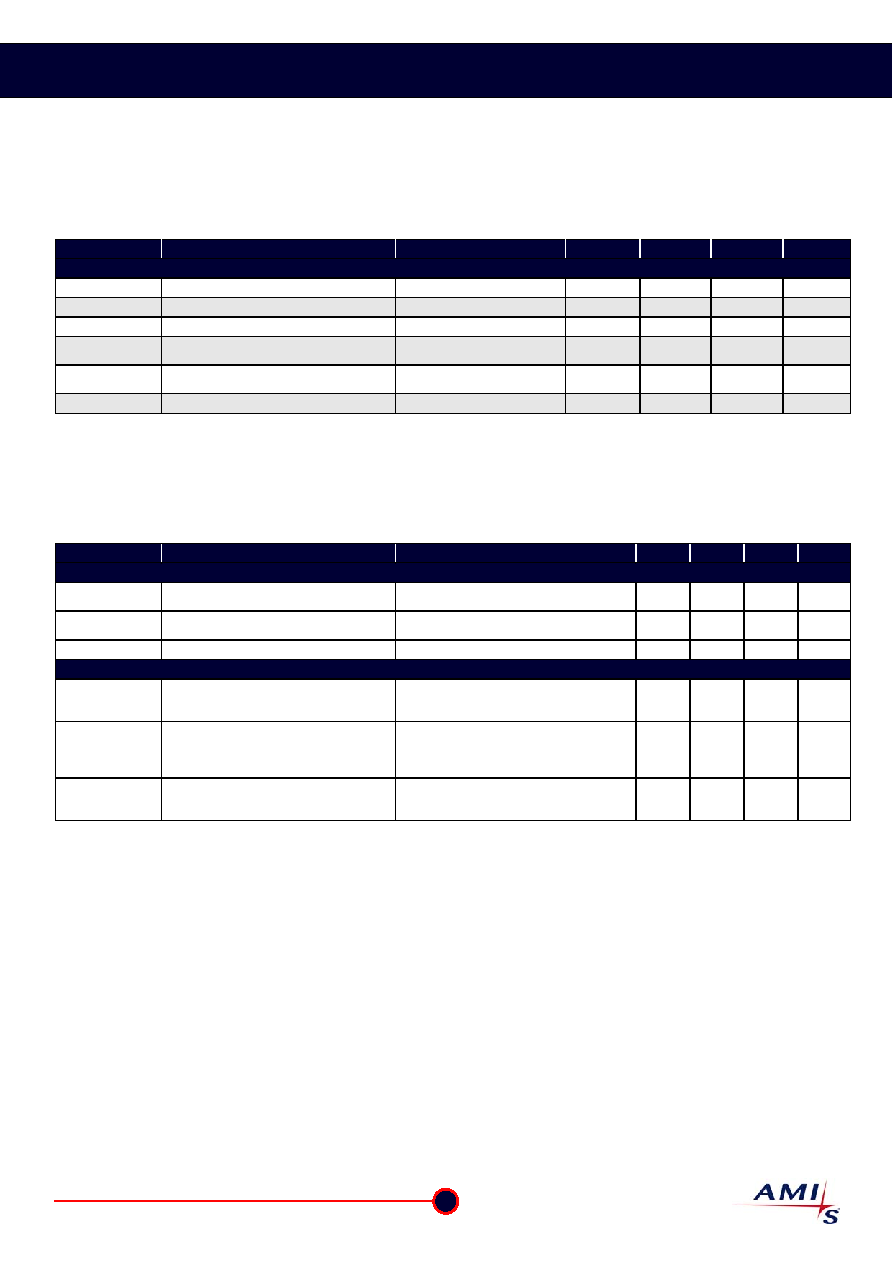
6.4 AC Electrical Characteristics
VCC = 4.75 to 5.25V; VBB = 7.3 to 18V; VEN > VEN,on ; Tamb = -40 to +125°C; RL = 500 unless specified otherwise.
Load for slope definitions (typical loads) = [L1] 1nF 1k
/ [L2] 6.8nF 600 / [L3] 10nF 500.
Table 7: AC Characteristics According to LIN V1.3
Symbol
Parameter
Conditions
Min.
Typ.
Max.
Unit
Dynamic Transceiver Characteristics According to LIN v1.3
t _slope_F
Slope time falling edge
See Figure 6
4
-
24
s
t _slope_R
Slope time rising edge
See Figure 6
4
-
24
s
t _slope _Sym
Slope time symmetry
t _slope_F - t _slope_R
-8
-
+8
s
T_rec_F
Propagation delay Bus dominant
to RxD = low; note 1
See Figure 5, 6
2
6
s
T_rec_R
Propagation delay Bus recessive
to RxD = high; note 1
See Figure 5, 6
2
6
s
tWAKE
Wake-up delay time
30
100
200
s
Notes:
1.
Not measured on ATE.
VCC = 4.75 to 5.25V; VBB = 7.3 to 18V; VEN > VEN,on ; Tamb = -40 to +125°C; RL = 500 unless specified otherwise.
Load for slope definitions (typical loads) = [L1] 1nF 1k
/ [L2] 6.8nF 600 / [L3] 10nF 500.
Table 8: AC Characteristics According to LIN V2.0
Symbol
Parameter
Conditions
Min.
Typ.
Max.
Unit
Dynamic Receiver Characteristics according to LIN v2.0
trx_pdr
Propagation delay bus dominant
to RxD = low; note 1
See Figure 7
6
s
trx_pdf
Propagation delay Bus recessive
to RxD = high; note 1
See Figure 7
6
s
trx_sym
Symmetry of receiver propagation delay
trx_pdr - trx_pdf
-2
-
+2
s
Dynamic Transmitter Characteristics according to LIN v2.0
D1
Duty cycle 1 = tBus_rec(min)/(2 x tBit);
See Figure 7
THRec(max)= 0.744 x Vbat;
THDom(max)= 0.581 x Vbat;
Vbat = 7.0V ... 18V; tBit= 50s
0.396
0.5
D1
Duty cycle 1 = tBus_rec(min)/(2 x tBit);
See Figure 7
THRec(max)= 0.744 x Vbat;
THDom(max)= 0.581 x Vbat;
Vbat = 7.0V; tBit= 50s;
tamb = -40°C
0.366
0.5
D2
Duty cycle 2 = tBus_rec(max)/(2 x tBit);
See Figure 7
THRec(min)= 0.284 x Vbat;
THDom(min)= 0.422 x Vbat;
Vbat = 7.6V ... 18V; tBit= 50s;
0.5
0.581
Notes:
1.
Not measured on ATE.
AMI Semiconductor
– Rev. 2.0, Apr. 2005
6
www.amis.com
相關(guān)PDF資料 |
PDF描述 |
|---|---|
| 0D6800 | FUME EXTRACTION UNIT AIR EX |
| 0D6802 | FILTER REPLACEMENT AIR EX |
| 0D6805 | SOLDER TWIN IRON CONNECT KIT |
| 0E7930A0 | SWITCH MOMEN PNL MT PB PU/PL |
| 0E7840A0 | PUSHBUTTON SWITCH, MOMENTARY, PANEL MOUNT |
相關(guān)代理商/技術(shù)參數(shù) |
參數(shù)描述 |
|---|---|
| 0C-6 | 制造商:LINE ELECTRIC 功能描述: 制造商:Line Electric 功能描述: |
| 0C621-003-XTD | 制造商:Rochester Electronics LLC 功能描述: 制造商:AppliedMicro 功能描述: 制造商:ON Semiconductor 功能描述: |
| 0C621-004-XTD | 制造商:ON Semiconductor 功能描述: |
| 0C622-003-XTD | 制造商:AppliedMicro 功能描述: |
| 0C622-004-XTD | 制造商:AppliedMicro 功能描述: |
發(fā)布緊急采購(gòu),3分鐘左右您將得到回復(fù)。