參數(shù)資料
| 型號: | XRT81L27IV-F |
| 廠商: | Exar Corporation |
| 文件頁數(shù): | 28/30頁 |
| 文件大?。?/td> | 0K |
| 描述: | IC LIU EI 7CH 3.3V 128TQFP |
| 標準包裝: | 72 |
| 應用: | DECT |
| 接口: | 串行 |
| 電源電壓: | 3.3V |
| 封裝/外殼: | 128-LQFP |
| 供應商設備封裝: | 128-TQFP(14x20) |
| 包裝: | 托盤 |
| 安裝類型: | 表面貼裝 |
第1頁第2頁第3頁第4頁第5頁第6頁第7頁第8頁第9頁第10頁第11頁第12頁第13頁第14頁第15頁第16頁第17頁第18頁第19頁第20頁第21頁第22頁第23頁第24頁第25頁第26頁第27頁當前第28頁第29頁第30頁
á
XRT81L27
SEVEN CHANNEL E1 LINE INTERFACE UNIT WITH CLOCK RECOVERY
REV. 1.1.0
5
43
TClk_6
I
Transmitter 6 Clock Input: E1 rate at 2.048MHz ± 50ppm.
44
TPOS_6/
TDATA_6
I
Transmitter 6 Positive Data/ NRZ Input: (see pin 38)
45
TNEG_6/
CODE_6
I-L
Transmitter 6 Negative Data Input: (see pin 39)
46
TAOS_6
I-L
Transmit All Ones Channel_6: (see pin 40)
47
SDO
LBM
O
I
Serial Data Output: (Host Mode)
This pin is the Serial Data Output port for the Microprocessor Serial
Interface access.
Loop-back Mode: (Hardware Mode)
When this pin is tied "High", Analog Local loop-back is selected.
Connect this pin "Low" to select remote loop-back. Digital Local loop-
back is not supported in Hardware Mode.
48
SDI
B1
I
Serial Data Input Port:
Host Mode, this pin is the serial data input port (see Figure 5).
Hardware Mode, B1, together with B2 (pin 49) and B3 (pin 50) are con-
trol bits used to select which one of the seven channels to be placed in
Loop-back mode. Analog or Remote Loop-back is determined by LBM
(pin 47).
49
SClk
B2
I
Microprocessor Serial Interface Clock:
Host Mode, this clock signal is used to clock SDI/SDO for the Serial
Interface.
Hardware Mode, B2, together with B1 and B3 are control bits to select
which of the seven channels to be placed in Loop-back mode.(see pin 48
description)
50
CS
B3
I
Chip Select Input:
Host Mode, this pin must be asserted "Low" in order to enable commu-
nication with the device via the Serial Interface.
Hardware Mode, B3, together with B1 and B2 are control bits to select
which of the seven channels to be placed in Loop-back mode. (see pin
48 description)
51
TAOS_5
I-L
Transmit All Ones Channel_5: (see pin 40)
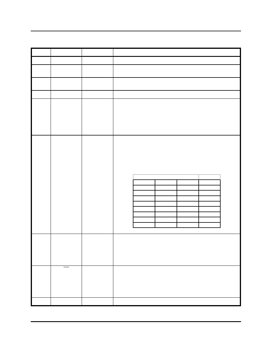
PIN DESCRIPTIONS
NOTE: I -H indicates an input pin with a 50k
pull-up Resistor, I-L indicates an input pin with a 50k pull-down resistor.
PIN #NAME
TYPE
DESCRIPTION
Loop-back Channel Control
B1
B2
B3
Chan. #
000
0
001
1
010
2
011
3
100
4
101
5
110
6
111
All
相關PDF資料 |
PDF描述 |
|---|---|
| XRT82D20IW-F | IC LIU E1 SGL 28SOJ |
| XRT82L24AIV-F | IC LIU E1 QAUD 100TQFP |
| XRT83D10IW | IC LIU T1/E1 SGL 28SOJ |
| XRT83L30IV-F | IC LIU LH/SH T1/E1 SGL 64TQFP |
| XRT83L314IB-L | IC LIU T1/E1/J1 14CH 304TBGA |
相關代理商/技術參數(shù) |
參數(shù)描述 |
|---|---|
| XR-T8205CP | 制造商:未知廠家 制造商全稱:未知廠家 功能描述:Telephone Ringer |
| XR-T8205P | 制造商:未知廠家 制造商全稱:未知廠家 功能描述:Telephone Ringer |
| XRT82D20 | 制造商:EXAR 制造商全稱:EXAR 功能描述:SINGLE CHANNEL E1 LINE INTERFACE UNIT |
| XRT82D20_06 | 制造商:EXAR 制造商全稱:EXAR 功能描述:SINGLE CHANNEL E1 LINE INTERFACE UNIT |
| XRT82D20ES | 功能描述:外圍驅動器與原件 - PCI 1 CH E1 LIU RoHS:否 制造商:PLX Technology 工作電源電壓: 最大工作溫度: 安裝風格:SMD/SMT 封裝 / 箱體:FCBGA-1156 封裝:Tray |
發(fā)布緊急采購,3分鐘左右您將得到回復。