- 您現(xiàn)在的位置:買賣IC網(wǎng) > PDF目錄372950 > XRT73L00A (Exar Corporation) E3/DS3/STS-1 LINE INTERFACE UNIT PDF資料下載
參數(shù)資料
| 型號(hào): | XRT73L00A |
| 廠商: | Exar Corporation |
| 英文描述: | E3/DS3/STS-1 LINE INTERFACE UNIT |
| 中文描述: | E3/DS3/STS-1線路接口單元 |
| 文件頁(yè)數(shù): | 28/53頁(yè) |
| 文件大?。?/td> | 604K |
| 代理商: | XRT73L00A |
第1頁(yè)第2頁(yè)第3頁(yè)第4頁(yè)第5頁(yè)第6頁(yè)第7頁(yè)第8頁(yè)第9頁(yè)第10頁(yè)第11頁(yè)第12頁(yè)第13頁(yè)第14頁(yè)第15頁(yè)第16頁(yè)第17頁(yè)第18頁(yè)第19頁(yè)第20頁(yè)第21頁(yè)第22頁(yè)第23頁(yè)第24頁(yè)第25頁(yè)第26頁(yè)第27頁(yè)當(dāng)前第28頁(yè)第29頁(yè)第30頁(yè)第31頁(yè)第32頁(yè)第33頁(yè)第34頁(yè)第35頁(yè)第36頁(yè)第37頁(yè)第38頁(yè)第39頁(yè)第40頁(yè)第41頁(yè)第42頁(yè)第43頁(yè)第44頁(yè)第45頁(yè)第46頁(yè)第47頁(yè)第48頁(yè)第49頁(yè)第50頁(yè)第51頁(yè)第52頁(yè)第53頁(yè)
XRT73L00
E3/DS3/STS-1 LINE INTERFACE UNIT
REV. 1.2.0
á
25
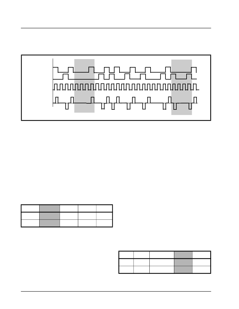
Figure 14 illustrates the HDB3 Encoder at work with
two separate strings of four (or more) consecutive ze-
ros.
2.3.3
Encoder
The XRT73L00 allows two methods to enable or dis-
able the HDB3/B3ZS Encoder.
If the XRT73L00 is operating in the Hardware
Mode.
To enable the HDB3/B3ZS Encoder, set the ENDEC-
DIS input pin (pin 21) to “0”. To disable the HDB3/
B3ZS Encoder, set the ENDECDIS input pin (pin 21)
to “1”.
If the XRT73L00 is operating in the HOST Mode.
To enable the HDB3/B3ZS Encoder, set the ENDEC-
DIS bit-field in Command Register (CR2) to “0”.
Enabling/Disabling the HDB3/B3ZS
To disable the HDB3/B3ZS Encoder, set the ENDEC-
DIS bit-field in Command Register (CR2) to “1”.
If either of these two methods is employed to disable
the HDB3/B3ZS Encoder, the LIU transmits the data
onto the line as it is received via the TPDATA and
TNDATA input pins.
2.4
T
HE
T
RANSMIT
P
ULSE
S
HAPER
C
IRCUITRY
The Transmit Pulse Shaper Circuitry consists of a
Transmit Line Build-Out circuit which can be enabled
or disabled by setting the TXLEV input pin or bit-field
to “High” or “Low”. The purpose of the Transmit Line
Build-Out circuit is to permit configuring of the
XRT73L00 to transmit an output pulse which is com-
pliant to either of the following Bellcore pulse tem-
plate requirements when measured at the Digital
Cross Connect System. Each of these Bellcore spec-
ifications further state that the cable length between
the Transmit Output and the Digital Cross Connect
system can range anywhere from 0 to 450 feet.
The Isolated DSX-3 Pulse Template Requirement per
Bellcore GR-499-CORE is illustrated in Figure 7.
The Isolated STSX-1 Pulse Template Requirement
per Bellcore GR-253-CORE is illustrated in Figure 8.
2.4.1
Enabling the Transmit Line Build-Out Cir-
cuit
If the Transmit Line Build-Out Circuit is enabled, the
XRT73L00 outputs shaped pulses onto the line via
the TTIP and TRING output pins.
Do the following to enable the Transmit Line Build-Out
circuit in the XRT73L00:
If the XRT73L00 is operating in the Hardware
Mode, set theTXLEV input pin (pin 1) to “Low”
If the XRT73L00 is operating in the HOST Mode,
set the TXLEV bit-field to “0” as illustrated below.
2.4.2
cuit
Disabling the Transmit Line Build-Out Cir-
F
IGURE
14. A
N
E
XAMPLE
OF
HDB3 E
NCODING
Data
TPDATA
TNDATA
1 0 1 1 0 0 0 0 0 1 1 1 1 0 1 1 0 1 1 0 0 1 1 0 0 0 0 1
0 0 0 V
Line Signal
B 0 0 V
TCLK
COMMAND REGISTER CR2 (ADDRESS = 0X02)
D4
D3
D2
D1
D0
Reserved ENDECDIS ALOSDIS DLOSDIS REQDIS
X
0
X
X
X
COMMAND REGISTER CR1 (ADDRESS = 0X01)
D4
D3
D2
D1
D0
TXOFF
TAOS
TXCLKINV
TXLEV
TXBIN
0
X
X
0
X
相關(guān)PDF資料 |
PDF描述 |
|---|---|
| XRT73L00AIV | E3/DS3/STS-1 LINE INTERFACE UNIT |
| XRT75L03DIV | Telecomm/Datacomm |
| XRT75L00 | E3/DS3/STS-1 LINE INTERFACE UNIT WITH JITTER ATTENUATOR |
| XRT75L00IV | E3/DS3/STS-1 LINE INTERFACE UNIT WITH JITTER ATTENUATOR |
| XRT75L03 | THREE CHANNEL E3/DS3/STS-1 LINE INTERFACE UNIT WITH JITTER ATTENUATOR |
相關(guān)代理商/技術(shù)參數(shù) |
參數(shù)描述 |
|---|---|
| XRT73L00AES | 功能描述:界面開(kāi)發(fā)工具 Eval System for XRT73L00A Series RoHS:否 制造商:Bourns 產(chǎn)品:Evaluation Boards 類型:RS-485 工具用于評(píng)估:ADM3485E 接口類型:RS-485 工作電源電壓:3.3 V |
| XRT73L00AIV | 制造商:EXAR 制造商全稱:EXAR 功能描述:E3/DS3/STS-1 LINE INTERFACE UNIT |
| XRT73L00IV | 制造商:未知廠家 制造商全稱:未知廠家 功能描述:LINE INTERFACE|QFP|44PIN|PLASTIC |
| XRT73L02M | 制造商:EXAR 制造商全稱:EXAR 功能描述:TWO CHANNEL E3/DS3/STS-1 LINE INTERFACE UNIT |
| XRT73L02MES | 功能描述:網(wǎng)絡(luò)控制器與處理器 IC RoHS:否 制造商:Micrel 產(chǎn)品:Controller Area Network (CAN) 收發(fā)器數(shù)量: 數(shù)據(jù)速率: 電源電流(最大值):595 mA 最大工作溫度:+ 85 C 安裝風(fēng)格:SMD/SMT 封裝 / 箱體:PBGA-400 封裝:Tray |
發(fā)布緊急采購(gòu),3分鐘左右您將得到回復(fù)。