- 您現(xiàn)在的位置:買(mǎi)賣(mài)IC網(wǎng) > PDF目錄372941 > XR17C158IV UART PDF資料下載
參數(shù)資料
| 型號(hào): | XR17C158IV |
| 英文描述: | UART |
| 中文描述: | 異步 |
| 文件頁(yè)數(shù): | 14/55頁(yè) |
| 文件大小: | 734K |
| 代理商: | XR17C158IV |
第1頁(yè)第2頁(yè)第3頁(yè)第4頁(yè)第5頁(yè)第6頁(yè)第7頁(yè)第8頁(yè)第9頁(yè)第10頁(yè)第11頁(yè)第12頁(yè)第13頁(yè)當(dāng)前第14頁(yè)第15頁(yè)第16頁(yè)第17頁(yè)第18頁(yè)第19頁(yè)第20頁(yè)第21頁(yè)第22頁(yè)第23頁(yè)第24頁(yè)第25頁(yè)第26頁(yè)第27頁(yè)第28頁(yè)第29頁(yè)第30頁(yè)第31頁(yè)第32頁(yè)第33頁(yè)第34頁(yè)第35頁(yè)第36頁(yè)第37頁(yè)第38頁(yè)第39頁(yè)第40頁(yè)第41頁(yè)第42頁(yè)第43頁(yè)第44頁(yè)第45頁(yè)第46頁(yè)第47頁(yè)第48頁(yè)第49頁(yè)第50頁(yè)第51頁(yè)第52頁(yè)第53頁(yè)第54頁(yè)第55頁(yè)
á
PCI BUS OCTAL UART
XR17C158
REV. 1.1.3
14
1.2.2
[TIMERMSB, TIMELSB, TIMER, TIMECNTL]
(
DEFAULT
0
X
XX-XX-00-00)
A 16-bit down-count timer for general purpose timer
or counter. Its clock source may be selected from in-
ternal crystal oscillator or externally on pin TMRCK.
The timer can be set to be a single-shot for a one-
time event or re-triggerable for continue interval. An
General Purpose 16-bit Timer/Counter.
interrupt may be generated in the INT Register when
the timer times out. It is controlled through 4 configu-
ration registers [TIMERCNTL, TIMER, TIMELSB,
TIMERMSB]. These registers provide start/stop and
re-triggerable or one-shot operation. The time-out
output of the Timer can be set to generate an inter-
rupt for system or event alarm.
T
ABLE
5: UART C
HANNEL
[7:0] I
NTERRUPT
S
OURCE
E
NCODING
P
RIORITY
B
IT
[
N
+2]
B
IT
[
N
+1]
B
IT
[
N
]
I
NTERRUPT
S
OURCE
(
S
)
x
1
2
3
4
5
6
7
0
0
0
0
1
1
1
1
0
0
1
1
0
0
1
1
0
1
0
1
0
1
0
1
None
RXRDY and RX Line Status (logic OR of LSR[4:1])
RXRDY Time-out
TXRDY, THR or TSR (auto RS485 mode) empty
MSR, RTS/CTS or DTR/DSR delta or Xoff/Xon det. or special char. detected
Reserved.
MPIO pin(s). Available only within channel 0, reserved in other channels.
TIMER Time-out. Available only within channel 0, reserved in other chan-
nels.
T
ABLE
6: UART C
HANNEL
[7:0] I
NTERRUPT
C
LEARING
:
RXRDY and RXRDY Time-out is clear by reading data in the RX FIFO until it falls below the trigger level.
RX Line Status interrupt clears after reading the LSR register.
TXRDY interrupt clears after reading ISR register that is in the UART channel register set.
Modem Status Register interrupt clears after reading MSR register that is in the UART channel register set.
RTS/CTS or DTR/DSR delta interrupt clears after reading MSR register that is in the UART channel register set.
Xoff/Xon delta and special character detect interrupt clears after reading the ISR register that is in the UART channel reg-
ister set.
TIMER Time-out interrupt clears after reading the TIMERCNTL register that is in the Device Configuration register set.
MPIO interrupt clears after reading the MPIOLVL register that is in the Device Configuration register set.
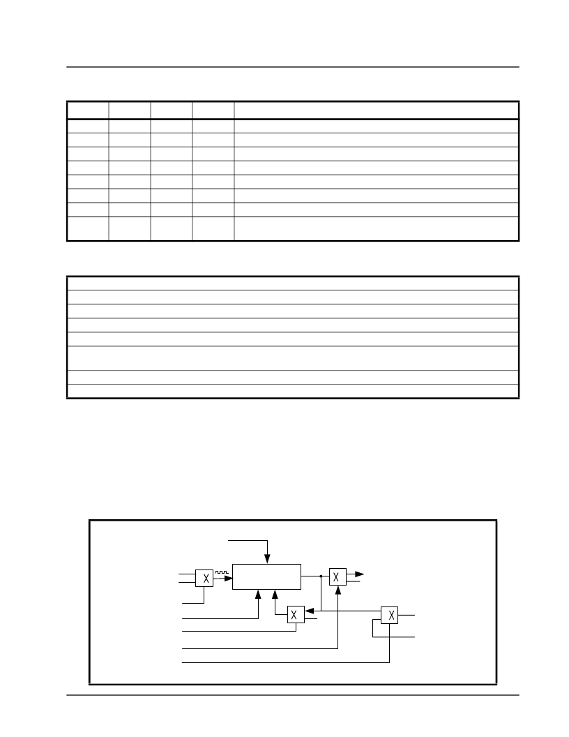
F
IGURE
5. T
IMER
/C
OUNTER
CIRCUIT
.
TMRCK
OSC. CLOCK
TIMERCNTL [3]
16-Bit
Timer/Counter
TIMERCNTL [2]
Re-trigger
Single-shot
TIMERCNTL [1]
Start/Stop
TIMERCNTL [0]
Timer Interrupt, Ch-0 INT=7
Time-out
Timer Interrupt Enable
Single/Re-triggerable
TIMERMSB and TIMERLSB
(16-bit Value)
0
1
0
1
0
1
No Interrupt
Clock
Select
TIMERCNTL [4]
0
1
MPIO[0]
MPIOLVL[0]
相關(guān)PDF資料 |
PDF描述 |
|---|---|
| XR215CP | IC-PHASE LOCKED LOOP |
| XR215 | Monolithic Phase Locked Loop |
| XR2206CP | IC-FUNCTION GENERATOR |
| XR2207MD | Waveform Generator/Support |
| XR2207CN | Waveform Generator/Support |
相關(guān)代理商/技術(shù)參數(shù) |
參數(shù)描述 |
|---|---|
| XR17C158IV-F | 功能描述:UART 接口集成電路 UART RoHS:否 制造商:Texas Instruments 通道數(shù)量:2 數(shù)據(jù)速率:3 Mbps 電源電壓-最大:3.6 V 電源電壓-最小:2.7 V 電源電流:20 mA 最大工作溫度:+ 85 C 最小工作溫度:- 40 C 封裝 / 箱體:LQFP-48 封裝:Reel |
| XR17C158IVTR-F | 制造商:Exar Corporation 功能描述:UART 8-CH 64Byte FIFO 5V 144-Pin LQFP T/R 制造商:Exar Corporation 功能描述:XR17C158IVTR-F |
| XR17D152 | 制造商:EXAR 制造商全稱:EXAR 功能描述:UNIVERSAL (3.3V AND 5V) PCI BUS DUAL UART |
| XR17D152CM | 制造商:EXAR 制造商全稱:EXAR 功能描述:UNIVERSAL (3.3V AND 5V) PCI BUS DUAL UART |
| XR17D152CM-0A-EVB | 功能描述:界面開(kāi)發(fā)工具 Supports D152 100 ld TQFP, PCI Interface RoHS:否 制造商:Bourns 產(chǎn)品:Evaluation Boards 類(lèi)型:RS-485 工具用于評(píng)估:ADM3485E 接口類(lèi)型:RS-485 工作電源電壓:3.3 V |
發(fā)布緊急采購(gòu),3分鐘左右您將得到回復(fù)。