- 您現(xiàn)在的位置:買賣IC網(wǎng) > PDF目錄384041 > UPD16772N (NEC Corp.) 480-OUTPUT TFT-LCD SOURCE DRIVER COMPATIBLE WITH 64-GRAY SCALES PDF資料下載
參數(shù)資料
| 型號: | UPD16772N |
| 廠商: | NEC Corp. |
| 英文描述: | 480-OUTPUT TFT-LCD SOURCE DRIVER COMPATIBLE WITH 64-GRAY SCALES |
| 中文描述: | 480輸出的TFT - LCD源驅(qū)動程序完全兼容64灰度 |
| 文件頁數(shù): | 13/20頁 |
| 文件大?。?/td> | 121K |
| 代理商: | UPD16772N |
Data Sheet S14416EJ1V0DS00
13
μ
PD16772
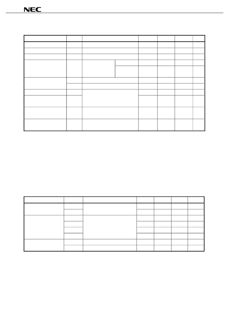
Electrical Characteristics (T
A
= –10 to +75
°
C, V
DD1
= 2.3 to 3.6 V, V
DD2
= 8.5 V
±
0.5 V, V
SS1
= V
SS2
= 0 V, unless
otherwise specified, the input level is defined to be LPC = L, Bcont = Open)
Parameter
Symbol
Condition
MIN.
TYP.
MAX.
Unit
Input Leak Current
I
IL
±
1.0
μ
A
High-Level Output Voltage
V
OH
STHR (STHL), I
OH
= 0 mA
V
DD1
– 0.1
V
Low-Level Output Voltage
V
OL
STHR (STHL), I
OL
= 0 mA
0.1
V
V
0
pin, V
5
pin
126
252
504
μ
A
γ
-Corrected Supply Current
I
γ
V
DD2
= 8.5 V
V
0
to V
4
= V
5
to V
9
=
4.0 V
V
4
pin, V
9
pin
–504
–252
–126
μ
A
I
VOH
V
X
= 7.0 V, V
OUT
= 6.5 V
Note
–30
μ
A
Driver Output Current
I
VOL
V
X
= 1.0 V, V
OUT
= 1.5 V
Note
30
μ
A
Output Voltage Deviation
V
O
±
7
±
20
mV
Output Swing Difference
Deviation
V
P–P
T
A
= 25
°
C
V
DD1
= 3.3 V, V
DD2
= 8.5 V
V
OUT
= 2.0 V, 4.25 V, 6.5 V
±
2
±
15
mV
Logic Part Dynamic Current
Consumption
I
DD1
V
DD1
1.0
7.5
mA
Driver Part Dynamic Current
Consumption
I
DD2
V
DD2
, with no load
3.5
7.5
mA
Note
V
X
refers to the output voltage of analog output pins S
1
to
S
480
.
V
OUT
refers to the voltage applied to analog output pins S
1
to S
480
.
Cautions 1. f
STB
= 50 kHz, f
CLK
= 40 MHz
2. The TYP. values refer to an all black or all white input pattern. The MAX. value refers to the
measured values in the dot checkerboard input pattern.
3. Refers to the current consumption per driver when cascades are connected under the
assumption of UXGA single-sided mounting (10 units).
Switching Characteristics (T
A
= –10 to +75
°
C, V
DD1
= 2.3 to 3.6 V, V
DD2
= 8.5 V
±
0.5 V, V
SS1
= V
SS2
= 0 V, unless
otherwise specified, the input level is defined to be LPC = L, Bcont = Open)
Parameter
Symbol
Condition
MIN.
TYP.
MAX.
Unit
t
PLH1
10
20
ns
Start Pulse Delay Time
t
PHL1
C
L
= 10 pF
10
20
ns
t
PLH2
2.5
5
μ
s
t
PLH3
5
8
μ
s
t
PHL2
2.5
5
μ
s
Driver Output Delay Time
t
PHL3
C
L
= 75 pF, R
L
= 5k
5
8
μ
s
C
I1
STHR (STHL) excluded, T
A
= 25°C
5
10
pF
Input Capacitance
C
I2
STHR (STHL),T
A
= 25°C
8
10
pF
#
#
#
#
#
#
#
相關(guān)PDF資料 |
PDF描述 |
|---|---|
| UPD168002GA-9EU | MONOLITHIC 6-CHANNEL H-BRIDGE DRIVER |
| UPD168002 | MONOLITHIC 6-CHANNEL H-BRIDGE DRIVER |
| UPD16804 | MONOLITHIC H BRIDGE DRIVER CIRCUIT |
| UPD16804GS | MONOLITHIC H BRIDGE DRIVER CIRCUIT |
| UPD16805 | MONOLITHIC H BRIDGE DRIVER CIRCUIT |
相關(guān)代理商/技術(shù)參數(shù) |
參數(shù)描述 |
|---|---|
| UPD16780 | 制造商:NEC 制造商全稱:NEC 功能描述:288/300 OUTPUT TFT-LCD SOURCE DRIVER |
| UPD16780A | 制造商:未知廠家 制造商全稱:未知廠家 功能描述:UPD16780A Data Sheet | Data Sheet[11/2000] |
| UPD16780N | 制造商:NEC 制造商全稱:NEC 功能描述:288/300 OUTPUT TFT-LCD SOURCE DRIVER |
| UPD16780N-XXX | 制造商:未知廠家 制造商全稱:未知廠家 功能描述:LCD Display Driver |
| UPD16781 | 制造商:未知廠家 制造商全稱:未知廠家 功能描述:UPD16781 Data Sheet | Data Sheet[02/2002] |
發(fā)布緊急采購,3分鐘左右您將得到回復(fù)。