- 您現(xiàn)在的位置:買賣IC網(wǎng) > Datasheet目錄57 > TSL13SM-LF (AMS-TAOS USA Inc)IC SENSOR LIGHT-VOLT SIDELK SMD Datasheet資料下載
參數(shù)資料
| 型號: | TSL13SM-LF |
| 廠商: | AMS-TAOS USA Inc |
| 文件頁數(shù): | 4/13頁 |
| 文件大?。?/td> | 620K |
| 描述: | IC SENSOR LIGHT-VOLT SIDELK SMD |
| 標(biāo)準(zhǔn)包裝: | 1 |
| 系列: | * |
| 其它名稱: | TSL13-SM-LFDKR |

TSL12S, TSL13S, TSL14S
LIGHT-TO-VOLTAGE CONVERTERS
TAOS051E SEPTEMBER 2007
3
The LUMENOLOGY r Company
r
r
Copyright E 2007, TAOS Inc.
www.taosinc.com
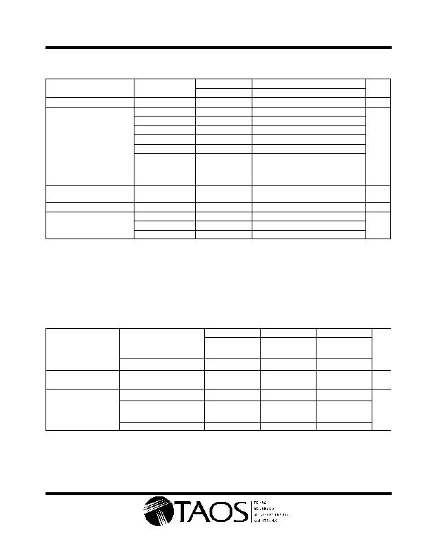
Electrical Characteristics at V
DD
= 5 V, T
A
= 25?/SPAN>C, ?/SPAN>
p
= 640 nm, R
L
= 10 k?/SPAN> (unless otherwise noted)
(see Notes 3, 4, 5)
TSL12S
TSL13S
TSL14S
PARAMETER
TEST CONDITIONS
MIN
TYP
MAX
MIN
TYP
MAX
MIN
TYP
MAX
UNIT
V
OM
Maximum output voltage
4.6
4.9
4.6
4.9
4.6
4.9
V
E
e
= 8 糤/cm
2
1.5
2
2.5
E
e
= 31 糤/cm
2
1.5
2
2.5
E
e
= 120 糤/cm
2
1.5
2
2.5
V
O
Output voltage
E
e
= 16 糤/cm
2
4
V
E
e
= 62 糤/cm
2
4
E
e
= 240 糤/cm
2
4
R
e
Irradiance responsivity
Note 6
248
64
16
mV/
(糤/
cm
2
)
V
OS
Extrapolated offset
voltage
Note 6
0.02
0.03
0.08
0.02
0.03
0.08
0.02
0.03
0.08
V
V
d
Dark voltage
E
e
= 0
0
0.08
0
0.08
0
0.08
V
E
e
= 8 糤/cm
2
1.1
1.7
I
D
Supply current
E
e
= 31 糤/cm
2
1.1
1.7
mA
D
E
e
= 120 糤/cm
2
1.1
1.7
NOTES: 3. Measurements are made with R
L
= 10 k?between output and ground.
4. Optical measurements are made using small-angle incident radiation from an LED optical source.
5. The 640 nm input irradiance E
e
is supplied by an AlInGaP LED with peak wavelength ?/DIV>
p
= 640 nm.
6. Irradiance responsivity is characterized over the range V
O
= 0.2 to 4 V. The best-fit straight line of Output Voltage V
O
versus
irradiance E
e
over this range may have a positive or negative extrapolated V
O
value for E
e
= 0. For low irradiance values, the output
voltage V
O
versus irradiance E
e
characteristic is non linear with a deviation toward V
O
= 0, E
e
= 0 origin from the best-fit straight
line referenced above.
Dynamic Characteristics at V
DD
= 5 V, T
A
= 25?/SPAN>C, ?/SPAN>
p
= 640 nm, R
L
= 10 k?/SPAN> (unless otherwise noted)
(see Figure 1)
TSL12S
TSL13S
TSL14S
PARAMETER
TEST CONDITIONS
MIN
TYP
MAX
MIN
TYP
MAX
MIN
TYP
MAX
UNIT
Output pulse delay
Min V
O
= 0 V; Peak V
O
= 2 V
13
1.7
0.9
t
dr
time for rising edge
(0% to 10%)
Min V
O
= 0.5 V; Peak V
O
= 2 V
2.3
1.2
0.6
約
Output pulse rise time
Min V
O
= 0 V; Peak V
O
= 2 V
20
7.2
2.6
t
r
(10% to 90%)
Min V
O
= 0.5 V; Peak V
O
= 2 V
10
6.5
2.9
約
Output pulse delay
Min V
O
= 0 V; Peak V
O
= 2 V
2.3
1.2
0.8
t
df
time for falling edge
(100% to 90%)
Min V
O
= 0.5 V; Peak V
O
= 2 V
2.2
1.1
0.7
約
Output pulse fall time
Min V
O
= 0 V; Peak V
O
= 2 V
10
6.8
2.9
t
f
u pu pu se a me
(90% to 10%)
Min V
O
= 0.5 V; Peak V
O
= 2 V
9
6.4
2.8
約
相關(guān)PDF資料 |
PDF描述 |
|---|---|
| TSL1401CL | IC LINEAR SENSOR ARRAY 128X1 CL |
| TSL1401CS-LF | IC OPTO SENSOR ARRAY CSP PCB MT |
| TSL1402R | IC LINEAR SENSOR ARRAY 256X1 |
| TSL1406RS | IC LINEAR SENSOR ARRAY 768X1 |
| TSL1410R | IC LINEAR SENSOR ARRAY 1280X1 |
相關(guān)代理商/技術(shù)參數(shù) |
參數(shù)描述 |
|---|---|
| TSL13T | 功能描述:光頻率和光電壓 Light to Voltage Converter RoHS:否 制造商:ams 峰值波長:1000 nm 工作電源電壓:5 V 最大工作溫度:+ 85 C 最小工作溫度:- 25 C 安裝風(fēng)格: 封裝 / 箱體: |
| TSL1401 | 制造商:Rochester Electronics LLC 功能描述:- Bulk |
| TSL1401BCS | 制造商:ams 功能描述:T&R / Chip Scale |
| TSL1401BCS-LF | 制造商:TAOS Inc 功能描述:IC OPTO SENSOR ARRAY CSP PCB MT 制造商:AMS 功能描述:replacement for: TSL1401CS-LF 制造商:ams 功能描述:Linear Sensor Array 128x1 Photodiodes |
| TSL1401CL | 功能描述:光頻率和光電壓 Linear Sensor Array 400dpi 128 pixel RoHS:否 制造商:ams 峰值波長:1000 nm 工作電源電壓:5 V 最大工作溫度:+ 85 C 最小工作溫度:- 25 C 安裝風(fēng)格: 封裝 / 箱體: |
發(fā)布緊急采購,3分鐘左右您將得到回復(fù)。