- 您現(xiàn)在的位置:買賣IC網(wǎng) > PDF目錄383966 > TS80C51RD2-VIE (International Rectifier) High Performance 8-bit Microcontroller PDF資料下載
參數(shù)資料
| 型號: | TS80C51RD2-VIE |
| 廠商: | International Rectifier |
| 英文描述: | High Performance 8-bit Microcontroller |
| 中文描述: | 高性能8位微控制器 |
| 文件頁數(shù): | 35/85頁 |
| 文件大小: | 762K |
| 代理商: | TS80C51RD2-VIE |
第1頁第2頁第3頁第4頁第5頁第6頁第7頁第8頁第9頁第10頁第11頁第12頁第13頁第14頁第15頁第16頁第17頁第18頁第19頁第20頁第21頁第22頁第23頁第24頁第25頁第26頁第27頁第28頁第29頁第30頁第31頁第32頁第33頁第34頁當(dāng)前第35頁第36頁第37頁第38頁第39頁第40頁第41頁第42頁第43頁第44頁第45頁第46頁第47頁第48頁第49頁第50頁第51頁第52頁第53頁第54頁第55頁第56頁第57頁第58頁第59頁第60頁第61頁第62頁第63頁第64頁第65頁第66頁第67頁第68頁第69頁第70頁第71頁第72頁第73頁第74頁第75頁第76頁第77頁第78頁第79頁第80頁第81頁第82頁第83頁第84頁第85頁
35
4188E–8051–08/06
AT/TS8xC51Rx2
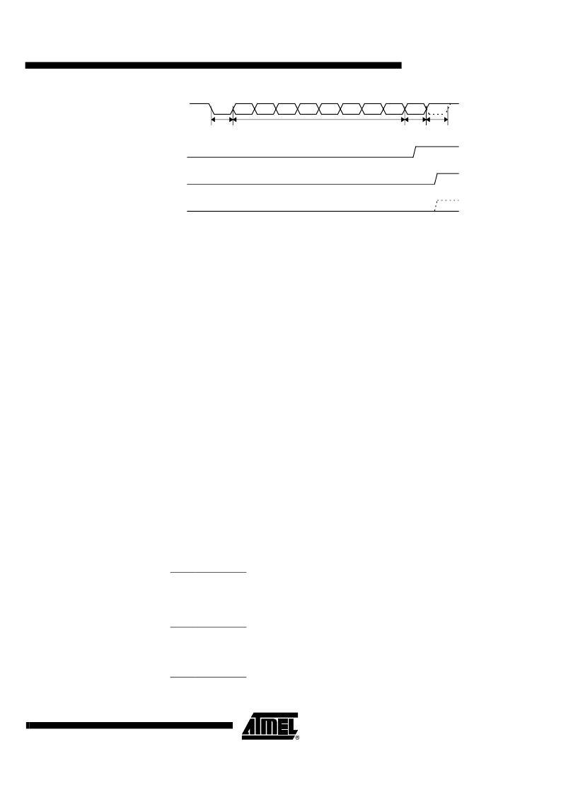
Figure 6-12.
UART Timings in Modes 2 and 3
6.4.2
Automatic Address Recognition
The automatic address recognition feature is enabled when the multiprocessor communication
feature is enabled (SM2 bit in SCON register is set).
Implemented in hardware, automatic address recognition enhances the multiprocessor commu-
nication feature by allowing the serial port to examine the address of each incoming command
frame. Only when the serial port recognizes its own address, the receiver sets RI bit in SCON
register to generate an interrupt. This ensures that the CPU is not interrupted by command
frames addressed to other devices.
If desired, you may enable the automatic address recognition feature in mode 1. In this configu-
ration, the stop bit takes the place of the ninth data bit. Bit RI is set only when the received
command frame address matches the device’s address and is terminated by a valid stop bit.
To support automatic address recognition, a device is identified by a given address and a broad-
cast address.
Note:
The multiprocessor communication and automatic address recognition features cannot be
enabled in mode 0 (i.e. setting SM2 bit in SCON register in mode 0 has no effect).
6.4.3
Given Address
Each device has an individual address that is specified in SADDR register; the SADEN register
is a mask byte that contains don’t-care bits (defined by zeros) to form the device’s given
address. The don’t-care bits provide the flexibility to address one or more slaves at a time. The
following example illustrates how a given address is formed.
To address a device by its individual address, the SADEN mask byte must be
1111 1111b
.
For example:
SADDR0101 0110b
SADEN1111 1100b
Given0101 01XXb
The following is an example of how to use given addresses to address different slaves:
Slave A:SADDR1111 0001b
SADEN1111 1010b
Given1111 0X0Xb
Slave B:SADDR1111 0011b
SADEN1111 1001b
Given1111 0XX1b
RI
SMOD0=0
Data byte
Ninth
bit
Stop
bit
Start
bit
RXD
D8
D7
D6
D5
D4
D3
D2
D1
D0
RI
SMOD0=1
FE
SMOD0=1
相關(guān)PDF資料 |
PDF描述 |
|---|---|
| TS83C51RB2-LCB | High Performance 8-bit Microcontroller |
| TS83C51RB2-LCE | High Performance 8-bit Microcontroller |
| TS83C51RB2-LIB | High Performance 8-bit Microcontroller |
| TS83C51RB2-LIE | High Performance 8-bit Microcontroller |
| TS83C51RB2-MCB | High Performance 8-bit Microcontroller |
相關(guān)代理商/技術(shù)參數(shù) |
參數(shù)描述 |
|---|---|
| TS80C51RD2-VIEB | 制造商:未知廠家 制造商全稱:未知廠家 功能描述:8-Bit Microcontroller |
| TS80C51RD2-VIED | 制造商:未知廠家 制造商全稱:未知廠家 功能描述:8-Bit Microcontroller |
| TS80C51RD2-VIER | 制造商:未知廠家 制造商全稱:未知廠家 功能描述:Microcontroller |
| TS80C51RD2-VIL | 制造商:ATMEL 制造商全稱:ATMEL Corporation 功能描述:High Performance 8-bit Microcontroller |
| TS80C51RD2-VILB | 制造商:未知廠家 制造商全稱:未知廠家 功能描述:8-Bit Microcontroller |
發(fā)布緊急采購,3分鐘左右您將得到回復(fù)。