- 您現(xiàn)在的位置:買賣IC網(wǎng) > PDF目錄383963 > TPS5211PWP (Texas Instruments, Inc.) HIGH FREQUENCY PROGRAMMABLE HYSTERETIC REGULATOR CONTROLLER PDF資料下載
參數(shù)資料
| 型號: | TPS5211PWP |
| 廠商: | Texas Instruments, Inc. |
| 英文描述: | HIGH FREQUENCY PROGRAMMABLE HYSTERETIC REGULATOR CONTROLLER |
| 中文描述: | 可編程滯高頻穩(wěn)壓控制器 |
| 文件頁數(shù): | 6/32頁 |
| 文件大?。?/td> | 469K |
| 代理商: | TPS5211PWP |
第1頁第2頁第3頁第4頁第5頁當(dāng)前第6頁第7頁第8頁第9頁第10頁第11頁第12頁第13頁第14頁第15頁第16頁第17頁第18頁第19頁第20頁第21頁第22頁第23頁第24頁第25頁第26頁第27頁第28頁第29頁第30頁第31頁第32頁
TPS5211
HIGH FREQUENCY PROGRAMMABLE HYSTERETIC
REGULATOR CONTROLLER
SLVS243 – SEPTEMBER 1999
6
POST OFFICE BOX 655303
DALLAS, TEXAS 75265
detailed description (continued)
power good
The power-good circuit monitors for an undervoltage condition on V
O
. If V
O
is 7% below V
REF
, then the PWRGD
pin is pulled low. PWRGD is an open-drain output.
overvoltage protection
The overvoltage protection (OVP) circuit monitors V
O
for an overvoltage condition. If V
O
is 15% above V
REF
,
then a fault latch is set and both output drivers are turned off. The latch will remain set until V
CC
goes below the
undervoltage lockout value. A 3-
μ
s deglitch timer is included for noise immunity. Refer to the
LODRV
section
for information on how to protect the microprocessor against overvoltages due to a shorted fault across the
high-side power FET.
overcurrent protection
The overcurrent protection (OCP) circuit monitors the current through the high-side FET. The overcurrent
threshold is adjustable with an external resistor divider between IOUT and ANAGND, with the divider voltage
connected to the OCP pin. If the voltage on OCP exceeds 100 mV, then a fault latch is set and the output drivers
are turned off. The latch will remain set until V
CC
goes below the undervoltage lockout value. A 3-
μ
s deglitch
timer is included for noise immunity.
The OCP circuit is also designed to protect the high-side power FET against
a short-to-ground fault on the terminal common to both power FETs.
drive regulator
The drive regulator provides drive voltage to the output drivers. The minimum drive voltage is 7 V. The minimum
short circuit current is 100 mA. Connect a
1-
μ
F ceramic capacitor from DRV to DRVGND.
LODRV
The LODRV circuit is designed to protect the microprocessor against overvoltages that can occur if the high-side
power FETs become shorted. External components to sense an overvoltage condition are required to use this
feature. When an overvoltage fault occurs, the low-side FETs are used as a crowbar. LODRV is pulled low and
the low-side FET will be turned on, overriding all control signals inside the TPS5211 controller. The crowbar
action will short the input supply to ground through the faulted high-side FETs and the low-side FETs. A fuse
in series with V
in
should be added to disconnect the short-circuit.
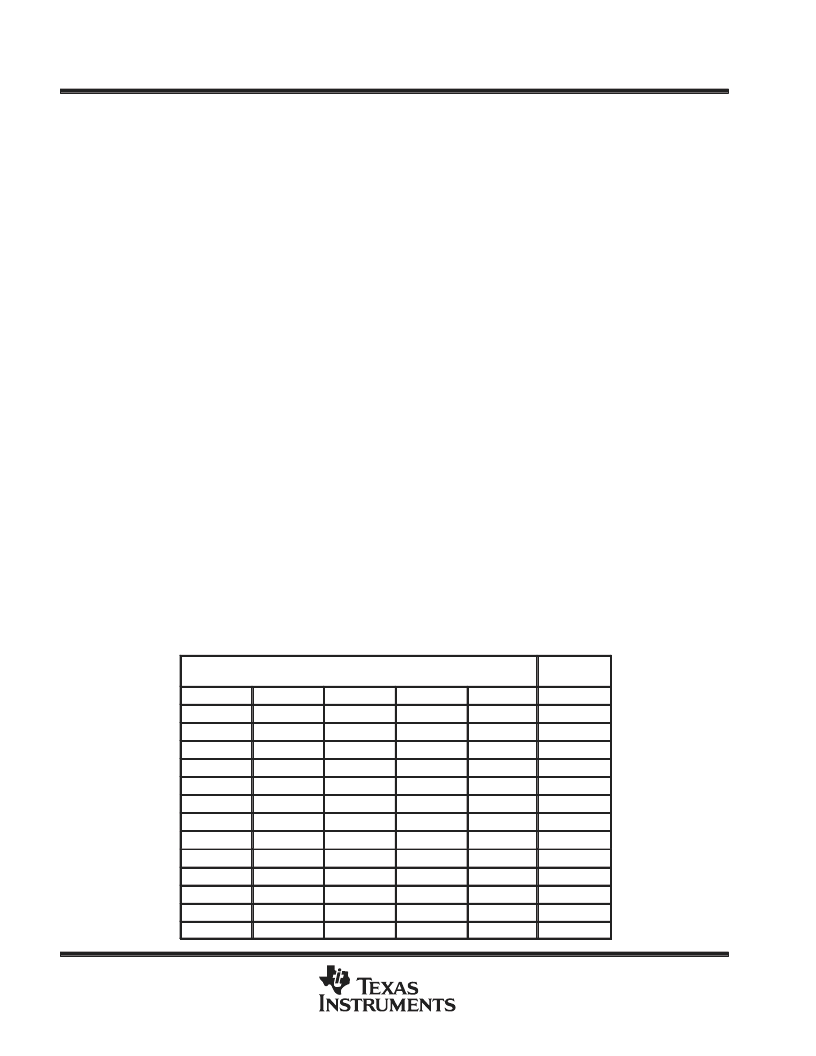
Table 1. Voltage Identification Codes
VID TERMINALS
(0 = GND, 1 = floating or pull-up to 5 V)
VREF
VID4
VID3
VID2
VID1
VID0
(Vdc)
0
1
1
1
1
1.30
0
1
1
1
0
1.35
0
1
1
0
1
1.40
0
1
1
0
0
1.45
0
1
0
1
1
1.50
0
1
0
1
0
1.55
0
1
0
0
1
1.60
0
1
0
0
0
1.65
0
0
1
1
1
1.70
0
0
1
1
0
1.75
0
0
1
0
1
1.80
0
0
1
0
0
1.85
0
0
0
1
1
1.90
相關(guān)PDF資料 |
PDF描述 |
|---|---|
| TPS60251RTW | HIGH EFFICIENCY CHARGE PUMP FOR 7 WLEDs WITH I2C INTERFACE |
| TPS61026DRC | 96% EFFICIENT SYNCHRONOUS BOOST CONVERTER |
| TPS61029DRC | 96% EFFICIENT SYNCHRONOUS BOOST CONVERTER |
| TPS61026DRCRG4 | 96% EFFICIENT SYNCHRONOUS BOOST CONVERTER |
| TPS61028DRC | 96% EFFICIENT SYNCHRONOUS BOOST CONVERTER |
相關(guān)代理商/技術(shù)參數(shù) |
參數(shù)描述 |
|---|---|
| TPS5211PWPR | 制造商:未知廠家 制造商全稱:未知廠家 功能描述:Analog IC |
| TPS524 | 制造商:未知廠家 制造商全稱:未知廠家 功能描述:PHOTOVOLTAIC CELL FOR THERMOPILE DETECTION |
| TPS5300 | 制造商:TI 制造商全稱:Texas Instruments 功能描述:MOBILE CPU POWER SUPPLY CONTROLLER |
| TPS5300DAP | 功能描述:DC/DC 開關(guān)控制器 Mobile CPU DC/DC Cntrlr RoHS:否 制造商:Texas Instruments 輸入電壓:6 V to 100 V 開關(guān)頻率: 輸出電壓:1.215 V to 80 V 輸出電流:3.5 A 輸出端數(shù)量:1 最大工作溫度:+ 125 C 安裝風(fēng)格: 封裝 / 箱體:CPAK |
| TPS5300DAPG4 | 功能描述:DC/DC 開關(guān)控制器 Mobile CPU DC/DC Cntrlr RoHS:否 制造商:Texas Instruments 輸入電壓:6 V to 100 V 開關(guān)頻率: 輸出電壓:1.215 V to 80 V 輸出電流:3.5 A 輸出端數(shù)量:1 最大工作溫度:+ 125 C 安裝風(fēng)格: 封裝 / 箱體:CPAK |
發(fā)布緊急采購,3分鐘左右您將得到回復(fù)。