- 您現在的位置:買賣IC網 > PDF目錄98266 > TMDS442PNP (TEXAS INSTRUMENTS INC) SPECIALTY CONSUMER CIRCUIT, PQFP128 PDF資料下載
參數資料
| 型號: | TMDS442PNP |
| 廠商: | TEXAS INSTRUMENTS INC |
| 元件分類: | 消費家電 |
| 英文描述: | SPECIALTY CONSUMER CIRCUIT, PQFP128 |
| 封裝: | GREEN, PLASTIC, TQFP-128 |
| 文件頁數: | 30/45頁 |
| 文件大小: | 1977K |
| 代理商: | TMDS442PNP |
第1頁第2頁第3頁第4頁第5頁第6頁第7頁第8頁第9頁第10頁第11頁第12頁第13頁第14頁第15頁第16頁第17頁第18頁第19頁第20頁第21頁第22頁第23頁第24頁第25頁第26頁第27頁第28頁第29頁當前第30頁第31頁第32頁第33頁第34頁第35頁第36頁第37頁第38頁第39頁第40頁第41頁第42頁第43頁第44頁第45頁
www.ti.com
T + k
RC
(2)
V(t)
+ V
DD
(1
* e*t RC)
(3)
SLLS757A – AUGUST 2006 – REVISED MARCH 2007
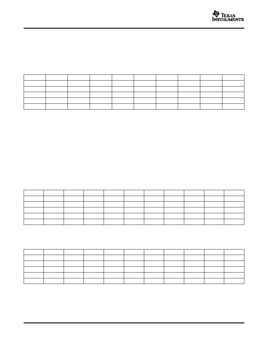
value, and C is the total load capacitance. The parameter, k, can be calculated from equation 3 by solving for
t, the times at which certain voltage thresholds are reached. Different input threshold combinations introduce
different values of t. Table 6 summarizes the possible values of k under different threshold combinations.
Table 6. Value K Upon Different Input Threshold Voltages
Vth-\Vth+
0.7VDD
0.65VDD
0.6VDD
0.55VDD
0.5VDD
0.45VDD
0.4VDD
0.35VDD
0.3VDD
0.1VDD
1.0986
0.9445
0.8109
0.6931
0.5878
0.4925
0.4055
0.3254
0.2513
0.15VDD
1.0415
0.8873
0.7538
0.6360
0.5306
0.4353
0.3483
0.2683
0.1942
0.2VDD
0.9808
0.8267
0.6931
0.5754
0.4700
0.3747
0.2877
0.2076
0.1335
0.25VDD
0.9163
0.7621
0.6286
0.5108
0.4055
0.3102
0.2231
0.1431
0.0690
0.3VDD
0.8473
0.6931
0.5596
0.4418
0.3365
0.2412
0.1542
0.0741
-
From equation 1, Rup(min) = 5.5V/3mA = 1.83 k to operate the bus under a 5-V pull-up voltage and provide less
than 3 mA when the I2C device is driving the bus to a low state. If a higher sink current, for example 4 mA, is
allowed, Rup(min) can be as low as 1.375 k.
Given a 5-V I2C device with input low and high threshold voltages at 0.3 Vdd and 0.7 Vdd, the valued of k is
0.8473 from Table 6. Taking into account the 1.83-k
pull-up resistor, the maximum total load capacitance is
C(total-5V) = 645 pF. Ccable(max) should be restricted to be less than 545 pF if Csource and Ci can be as heavy as 50
pF. Here the Ci is treated as Csink, the load capacitance of a sink device.
Fixing the maximum transition time from Table 6, T = 1
μs, and using the k values from Table 6, the
recommended maximum total resistance of the pull-up resistors on an I2C bus can be calculated for different
system setups.
To support the maximum load capacitance specified in the HDMI spec, Ccable(max) = 700pF/Csource = 50pF/Ci =
Table 7. Pull-Up Resistor Upon Different Threshold Voltages and 800-pF Loads
Vth-\Vth+
0.7VDD
0.65VDD
0.6VDD
0.55VDD
0.5VDD
0.45VDD
0.4VDD
0.35VDD
0.3VDD
UNIT
0.1VDD
1.14
1.32
1.54
1.80
2.13
2.54
3.08
3.84
4.97
k
0.15VDD
1.20
1.41
1.66
1.97
2.36
2.87
3.59
4.66
6.44
k
0.2VDD
1.27
1.51
1.80
2.17
2.66
3.34
4.35
6.02
9.36
k
0.25VDD
1.36
1.64
1.99
2.45
3.08
4.03
5.60
8.74
18.12
k
0.3VDD
1.48
1.80
2.23
2.83
3.72
5.18
8.11
16.87
-
k
Or, limiting the maximum load capacitance of each cable to be 400 pF to accommodate with I2C spec version
2.1. Ccable(max) = 400pF/Csource=50pF/Ci = 50pF, the maximum values of R are calculated as shown in Table 8.
Table 8. Pull-Up Resistor Upon Different Threshold Voltages and 500-pF Loads
Vth-\Vth+
0.7VDD
0.65VDD
0.6VDD
0.55VDD
0.5VDD
0.45VDD
0.4VDD
0.35VDD
0.3VDD
UNIT
0.1VDD
1.82
2.12
2.47
2.89
3.40
4.06
4.93
6.15
7.96
k
0.15VDD
1.92
2.25
2.65
3.14
3.77
4.59
5.74
7.46
10.30
k
0.2VDD
2.04
2.42
2.89
3.48
4.26
5.34
6.95
9.63
14.98
k
0.25VDD
2.18
2.62
3.18
3.92
4.93
6.45
8.96
13.98
28.99
k
0.3VDD
2.36
2.89
3.57
4.53
5.94
8.29
12.97
26.99
-
k
Obviously, to accommodate the 3-mA drive current specification, a narrower threshold voltage range is required
to support a maximum 800-pF load capacitance for a standard-mode I2C bus.
When the input low and high level threshold voltages, Vth- and Vth+, are 0.7 V and 1.9 V, which is 0.15 VDD and
0.4 VDD approximately with VDD = 5 V, from Table 7, the maximum pull-up resistor is 3.59 k. The allowable
pull-up resistor is in the range of 1.83 k
and 3.59 k.
36
Copyright 2006–2007, Texas Instruments Incorporated
Product Folder Link(s): TMDS442
相關PDF資料 |
PDF描述 |
|---|---|
| TMDS442PNPRG4 | SPECIALTY CONSUMER CIRCUIT, PQFP128 |
| TMDS461PZIT | SPECIALTY CONSUMER CIRCUIT, PQFP100 |
| TMDS461PZT | SPECIALTY CONSUMER CIRCUIT, PQFP100 |
| TMDS461PZTR | SPECIALTY CONSUMER CIRCUIT, PQFP100 |
| TMP431BDGKT | SPECIALTY ANALOG CIRCUIT, PDSO8 |
相關代理商/技術參數 |
參數描述 |
|---|---|
| TMDS442PNPG4 | 功能描述:多路器開關 IC 4-to-2 DVI/HDMI Sw RoHS:否 制造商:Texas Instruments 通道數量:1 開關數量:4 開啟電阻(最大值):7 Ohms 開啟時間(最大值): 關閉時間(最大值): 傳播延遲時間:0.25 ns 工作電源電壓:2.3 V to 3.6 V 工作電源電流: 最大工作溫度:+ 85 C 安裝風格:SMD/SMT 封裝 / 箱體:UQFN-16 |
| TMDS442PNPR | 功能描述:視頻開關 IC 4-to-2 DVI/HDMI Sw Pwr I/O Exp RoHS:否 制造商:Texas Instruments 開關數量:4 開啟電阻(最大值):12 Ohms 傳播延遲時間: 開啟時間(最大值): 關閉時間(最大值): 最大工作溫度:+ 85 C 最小工作溫度:- 40 C 封裝 / 箱體:WQFN-42 封裝:Reel |
| TMDS442PNPRG4 | 功能描述:視頻開關 IC 4-to-2 DVI/HDMI Sw Pwr I/O Exp RoHS:否 制造商:Texas Instruments 開關數量:4 開啟電阻(最大值):12 Ohms 傳播延遲時間: 開啟時間(最大值): 關閉時間(最大值): 最大工作溫度:+ 85 C 最小工作溫度:- 40 C 封裝 / 箱體:WQFN-42 封裝:Reel |
| TMDS461 | 制造商:TI 制造商全稱:Texas Instruments 功能描述:1080p a?? Deep Color 4-to-1 HDMI/DVI Switch with Adaptive Equalization |
| TMDS461PZT | 功能描述:視頻開關 IC 4 to 1 HDMI Switch RoHS:否 制造商:Texas Instruments 開關數量:4 開啟電阻(最大值):12 Ohms 傳播延遲時間: 開啟時間(最大值): 關閉時間(最大值): 最大工作溫度:+ 85 C 最小工作溫度:- 40 C 封裝 / 箱體:WQFN-42 封裝:Reel |
發(fā)布緊急采購,3分鐘左右您將得到回復。