- 您現(xiàn)在的位置:買(mǎi)賣(mài)IC網(wǎng) > PDF目錄383959 > TMC22051AKHC (FAIRCHILD SEMICONDUCTOR CORP) Circular Connector; No. of Contacts:11; Series:MS27484; Body Material:Aluminum; Connecting Termination:Crimp; Connector Shell Size:18; Circular Contact Gender:Pin; Circular Shell Style:Straight Plug; Insert Arrangement:18-11 RoHS Compliant: No PDF資料下載
參數(shù)資料
第1頁(yè)第2頁(yè)第3頁(yè)第4頁(yè)第5頁(yè)第6頁(yè)當(dāng)前第7頁(yè)第8頁(yè)第9頁(yè)第10頁(yè)第11頁(yè)第12頁(yè)第13頁(yè)第14頁(yè)第15頁(yè)第16頁(yè)第17頁(yè)第18頁(yè)第19頁(yè)第20頁(yè)第21頁(yè)第22頁(yè)第23頁(yè)第24頁(yè)第25頁(yè)第26頁(yè)第27頁(yè)第28頁(yè)第29頁(yè)第30頁(yè)第31頁(yè)第32頁(yè)第33頁(yè)第34頁(yè)第35頁(yè)第36頁(yè)第37頁(yè)第38頁(yè)第39頁(yè)第40頁(yè)第41頁(yè)第42頁(yè)第43頁(yè)第44頁(yè)第45頁(yè)第46頁(yè)第47頁(yè)第48頁(yè)第49頁(yè)第50頁(yè)第51頁(yè)第52頁(yè)第53頁(yè)第54頁(yè)第55頁(yè)第56頁(yè)第57頁(yè)第58頁(yè)第59頁(yè)第60頁(yè)第61頁(yè)第62頁(yè)第63頁(yè)第64頁(yè)第65頁(yè)第66頁(yè)第67頁(yè)第68頁(yè)第69頁(yè)第70頁(yè)第71頁(yè)第72頁(yè)第73頁(yè)第74頁(yè)第75頁(yè)第76頁(yè)第77頁(yè)第78頁(yè)第79頁(yè)第80頁(yè)第81頁(yè)第82頁(yè)第83頁(yè)第84頁(yè)
PRODUCT SPECIFICATION
TMC22x5yA
REV. 1.0.0 2/4/03
7
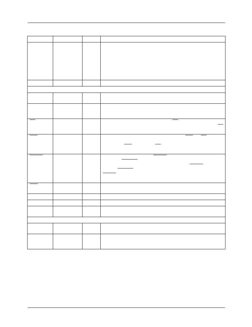
DREF
30
TTL
Decoder reference signal.
This is a dual function pin, controlled by
register 24, that can function as an active video output indicator or
output as a clamp pulse. When set to the active video output function,
the DREF pin is HIGH during the video portion of each line and LOW
during the horizontal and vertical blanking levels. When set to output a
clamp pulse, the clamp pulse is controlled by register 24 and 25
allowing a user to program when a 0.5
μ
Sec pulse is output relative to
HSYNC.
Field identification output.
A 3 bit field ident from the DRS signal.
FID
2-0
μ
P Interface
D
7-0
33, 32, 31
TTL
45, 44, 43, 42,
41, 38, 37, 36
63, 62
TTL
Parallel control port data I/O.
All control parameters are loaded into
and read back over this 8 bit data port.
Parallel control port address inputs.
These pins govern whether the
microprocessor interface selects a table/register address or reads/
writes table/register contents.
Parallel control port chip select.
When CS is high the microprocessor
interface port, D
7-0
, is set to HIGH impedance and ignored. When CS
is LOW, the microprocessor can read or write parameters over D
7-0
.
Parallel control port read/write control.
When R/W and CS are LOW,
the microprocessor can write to the control registers or XLUT over
D
7-0
. When R/W is HIGH and CS is LOW, it can read the contents of
any selected XLUT address or control register over D
7-0
.
Chip master reset.
Bringing RESET LOW sets the software reset
control bit, SRESET, LOW and disables the digital outputs. If HRESET
is LOW the decoder outputs remain disabled after RESET goes HIGH
until the SRESET bit is set high by the host. If HRESET is HIGH when
RESET goes HIGH the decoder the internal state machines are
enabled.
Serial/parallel interface select.
This pin will select between a parallel
(HIGH) or serial (LOW) interface port.
Serial data interface.
Bi-directional serial interface to the control port.
Serial interface clock.
Serial Address.
Three bits providing the lsbs of the serial chip ID used
to identify the decoder.
A
1-0
TTL
CS
60
TTL
R/W
61
TTL
RESET
51
TTL
SER
53
TTL
SDA
SCL
SA
2-0
58
59
R-Bus
R-Bus
TTL
56, 55, 54
Power Supply
V
DD
5, 17, 29, 40,
47, 65, 91
4, 16, 28, 39,
46, 57, 64, 76,
90, 92
+5 V
Power Supply.
Positive power supply for digital circuits, +5V.
GND
0.0 V
Ground.
Ground for digital circuits, 0V.
Pin Descriptions
(cont.)
Pin Name
Pin Number
Value
Pin Function Description
相關(guān)PDF資料 |
PDF描述 |
|---|---|
| TMC22X5YA | Multistandard Digital Video Decoder Three-Line Adaptive Comb Decoder Family, 8 & 10 bit |
| TMC22052AKHC | Multistandard Digital Video Decoder Three-Line Adaptive Comb Decoder Family, 8 & 10 bit |
| TMC22053AKHC | Multistandard Digital Video Decoder Three-Line Adaptive Comb Decoder Family, 8 & 10 bit |
| TMC22151AKHC | Multistandard Digital Video Decoder Three-Line Adaptive Comb Decoder Family, 8 & 10 bit |
| TMC22152AKHC | Multistandard Digital Video Decoder Three-Line Adaptive Comb Decoder Family, 8 & 10 bit |
相關(guān)代理商/技術(shù)參數(shù) |
參數(shù)描述 |
|---|---|
| TMC22052AKHC | 制造商:FAIRCHILD 制造商全稱:Fairchild Semiconductor 功能描述:Multistandard Digital Video Decoder Three-Line Adaptive Comb Decoder Family, 8 & 10 bit |
| TMC22053AKHC | 制造商:Rochester Electronics LLC 功能描述:- Bulk |
| TMC22053KHC | 制造商:Rochester Electronics LLC 功能描述:- Bulk 制造商:Fairchild Semiconductor Corporation 功能描述: |
| TMC22071A | 制造商:CADEKA 制造商全稱:CADEKA 功能描述:Genlocking Video Digitizer |
| TMC22071AKHC | 功能描述:視頻 IC Video Digitizer Genlocking RoHS:否 制造商:Fairchild Semiconductor 工作電源電壓:5 V 電源電流:80 mA 最大工作溫度:+ 85 C 封裝 / 箱體:TSSOP-28 封裝:Reel |
發(fā)布緊急采購(gòu),3分鐘左右您將得到回復(fù)。