- 您現(xiàn)在的位置:買賣IC網(wǎng) > PDF目錄383997 > TIBPAL16R6-7MFK (Texas Instruments, Inc.) HIGH-PERFORMANCE IMPACT-X E PAL CIRCUITS PDF資料下載
參數(shù)資料
| 型號: | TIBPAL16R6-7MFK |
| 廠商: | Texas Instruments, Inc. |
| 英文描述: | HIGH-PERFORMANCE IMPACT-X E PAL CIRCUITS |
| 中文描述: | 高性能影響組E PAL制式電路 |
| 文件頁數(shù): | 13/30頁 |
| 文件大?。?/td> | 295K |
| 代理商: | TIBPAL16R6-7MFK |
第1頁第2頁第3頁第4頁第5頁第6頁第7頁第8頁第9頁第10頁第11頁第12頁當(dāng)前第13頁第14頁第15頁第16頁第17頁第18頁第19頁第20頁第21頁第22頁第23頁第24頁第25頁第26頁第27頁第28頁第29頁第30頁
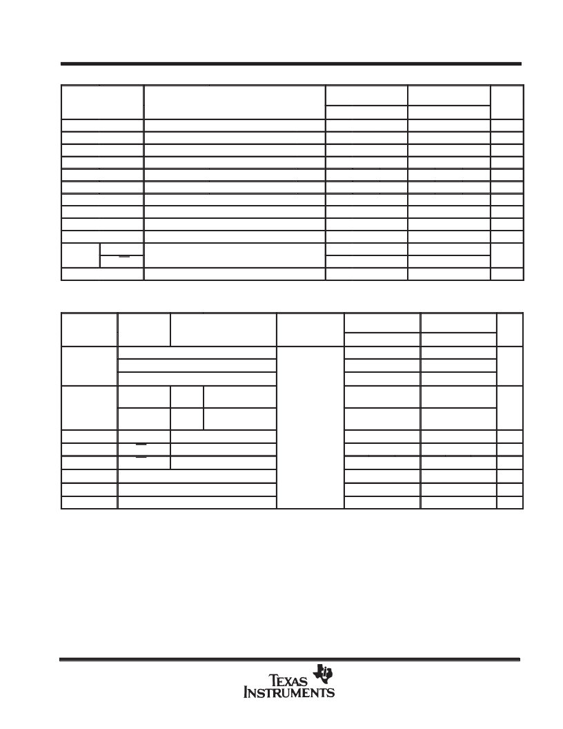
PARAMETER
TEST CONDITIONS
UNIT
VI = 2 V
f = 1 MHz,
Ci
pF
UNIT
PARAMETER
FROM
(INPUT)
TO
(OUTPUT)
TEST
CONDITIONS
R1 = 200
,
R2 = 200
,
See Figure 8
tpd
ns
TIBPAL16R8-5C
HIGH-PERFORMANCE
IMPACT-X
PAL
CIRCUITS
SRPS011D – D3359, OCTOBER 1989 – REVISED SEPTEMBER 1992
POST OFFICE BOX 655303
DALLAS, TEXAS 75265
13
PRODUCTION DATA information is current as of publication date.
Products conform to specifications per the terms of Texas Instruments
standard warranty. Production processing does not necessarily
electrical characteristics over recommended operating free-air temperature range
TIBPAL16R8-5CFN
TIBPAL16R8-5CJ
TIBPAL16R8-5CN
TYP
–0.8
MIN
TYP
–0.8
MAX
–1.5
MIN
MAX
–1.5
VIK
VOH
VOL
IOZH
IOZL
II
IIH
IIL
IOS
ICC
VCC = 4.75 V,
VCC = 4.75 V,
VCC = 4.75 V,
VCC = 5.25 V,
VCC = 5.25 V,
VCC = 5.25 V,
VCC = 5.25 V,
VCC = 5.25 V,
VCC = 5.25 V,
VCC = 5.25 V,
II = –18 mA
IOH = –3.2 mA
IOL = 24 mA
VO = 2.7 V
VO = 0.4 V
VI = 5.5 V
VI = 2.7 V
VI = 0.4 V
VO = 0.5 V
VI = 0, Outputs open
V
2.4
2.7
2.4
2.7
V
0.3
0.5
0.3
0.5
V
μ
A
μ
A
μ
A
μ
A
μ
A
mA
100
100
–100
–100
100
100
25
25
–250
–250
–30
–70
–130
–30
–70
–130
180
180
mA
I
8.5
6.5
CLK/OE
7.5
5.5
Co
f = 1 MHz,
VO = 2 V
10
8
pF
switching characteristics
over recommended ranges of supply voltage and operating free-air
temperature (unless otherwise noted)
TIBPAL16R8-5CFN
TIBPAL16R8-5CJ
TIBPAL16R8-5CN
TYP
125
MIN
125
TYP
MAX
MIN
MAX
without feedback
fmax§
with internal feedback (counter configuration)
125
125
MHz
with external feedback
117
111
CLK
↑
Q
with up to 4 outputs
switching
1.5
4
1.5
4
CLK
↑
Q
with more than 4
outputs switching
1.5
4
1.5
4.5
tpd
ten
tdis
tr
tf
tsk(o)#
CLK
↑
OE
↓
OE
↑
Internal feedback
3.5
3.5
ns
Q
1.5
6
1.5
6
ns
Q
1
6.5
1
7
ns
1.5
1.5
ns
1.5
1.5
ns
Skew between outputs
0.5
0.5
ns
All typical values are at VCC = 5 V, TA = 25
°
C.
Not more than one output should be shorted at a time, and the duration of the short circuit should not exceed one second. VO is set at 0.5 V to
avoid test problems caused by test equipment ground degradation.
§See ’fmax Specification’ near the end of this data sheet.
This parameter is calculated from the measured fmax with internal feedback in a counter configuration (see Figure 2 for illustration).
#tsk(o) is the skew time between registered outputs.
相關(guān)PDF資料 |
PDF描述 |
|---|---|
| TIBPAL16R6-7MJ | HIGH-PERFORMANCE IMPACT-X E PAL CIRCUITS |
| TIL189-2 | OPTOCOUPLERS/OPTOISOLATORS |
| TIL311A | HEXDECIMAL DISPLAY WITH LOGIC |
| TIL318 | P-N GALLIUM ARSENIDE INFRARED-EMITTING DIODES |
| TIL33B | P-N GALLIUM ARSENIDE INFRARED-EMITTING DIODES |
相關(guān)代理商/技術(shù)參數(shù) |
參數(shù)描述 |
|---|---|
| TIBPAL16R6-7MJ | 制造商:TI 制造商全稱:Texas Instruments 功能描述:HIGH-PERFORMANCE IMPACT-X E PAL CIRCUITS |
| TIBPAL16R8-10C | 制造商:TI 制造商全稱:Texas Instruments 功能描述:HIGH-PERFORMANCE IMPACT-X E PAL CIRCUITS |
| TIBPAL16R8-10CFN | 制造商:TI 制造商全稱:Texas Instruments 功能描述:HIGH-PERFORMANCE IMPACT-X E PAL CIRCUITS |
| TIBPAL16R8-10CJ | 制造商:TI 制造商全稱:Texas Instruments 功能描述:HIGH-PERFORMANCE IMPACT-X E PAL CIRCUITS |
| TIBPAL16R8-10CN | 制造商:TI 制造商全稱:Texas Instruments 功能描述:HIGH-PERFORMANCE IMPACT-X E PAL CIRCUITS |
發(fā)布緊急采購,3分鐘左右您將得到回復(fù)。