- 您現(xiàn)在的位置:買賣IC網(wǎng) > PDF目錄297490 > T630 (Dynex Semiconductor Ltd.) Radiation hard 16-Bit ParallelError Detection & Correction PDF資料下載
參數(shù)資料
| 型號(hào): | T630 |
| 廠商: | Dynex Semiconductor Ltd. |
| 英文描述: | Radiation hard 16-Bit ParallelError Detection & Correction |
| 中文描述: | 輻射硬16位ParallelError檢測(cè) |
| 文件頁數(shù): | 3/10頁 |
| 文件大小: | 92K |
| 代理商: | T630 |
54HSC/T630
2/10
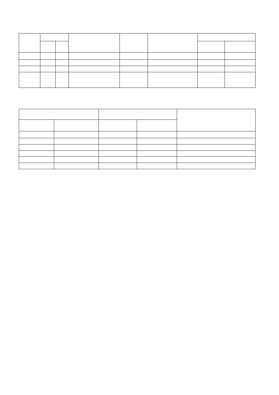
Table 1: Control Functions
Control
Error Flags
Cycle
S1
S0
EDAC Function
Data UO
Checkword
SEF
DEF
WRITE
Low
Generates Checkword
Input Data
Output Checkword
Low
READ
Low
High
Read Data BCheckword
Input Data
Input Checkword
Low
READ
High
Latch & Flag Error
Latch Data
Latch Checkword
Enabled
READ
High
Low
Correct Data Word &
Output
Output Syndrome Bits
Enabled
Generate Syndrome Bits
Corrected
Data
Table 2: Error Functions
Total Number of Errors
Error Flags
Data Correction
16-bit Data
6-bit Checkword
SEF
DEF
0
Low
Not Applicable
1
0
High
Low
Correctlon
0
1
High
Low
Correction
1
High
Interrupt
2
0
High
Interrupt
0
2
High
Interrupt
ERROR DETECTION & CORRECTION
During a memory write cycle, six check bits (CBO-CB5)
are generated by eight-input parity generators using the data
bits defined in Table 3. During a memory read cycle, the 6-bit
checkword is retrieved along with the actual data.
Error detection is accomplished as the 6-bit checkword and
the 16-bit data word from memory are applied to internal parity
generators/checkers. If the parity of all six groupings of data
and check bits are correct, it is assumed that no error has
occurred and both error flags will be low. It should be noted
that the sense of two of the check bits, bits CBO and CB1, is
inverted to ensure that the gross-error condition of all lows and
all highs is detected.
If the parity of one or more of the check groups is incorrect,
an error has occurred and the proper error flag or flags will be
set high. Any single error in the 16bit data word will change the
sense of exactly three bits of the 6-bit checkword. Any single
error in the 6bit checkword changes the sense of only that one
bit. In either case, the single error flag will be set high while the
dual error flag will remain low.
Any two-bit error will change the sense of an even number
of check bits. The two-bit error is not correctable since the
parity tree can only identify singlebit errors. Both error flags are
set high when any two-bit error is detected.
Three or more simultaneous bit errors cause the EDAC to
transmit that no error, a correctable error, or an uncorrectable
error has occurred and hence produce erroneous results in all
three cases.
Error correction is accomplished by identifying the bad bit
and inverting it. Identification of the erroneous bit is achieved
by comparing the 16-bit word and 6-bit checkword from
memory with the new checkword with one (checkword error)
or three (data word error) inverted bits.
As the corrected word is made available on the data word l/
O port, the checkword l/O port presents a 6-bit syndrome error
code. This syndrome code can be used to identify the
corrupted bit in memory (see Table 4. overleaf).
相關(guān)PDF資料 |
PDF描述 |
|---|---|
| T6A6CI | Bi-Directional Triode Thyristor 6A Mold TRIAC |
| T70HFL10S10 | 70 A, 100 V, SILICON, RECTIFIER DIODE |
| T7NS5D1-18 | POWER/SIGNAL RELAY, SPDT, MOMENTARY, 0.02A (COIL), 18VDC (COIL), 360mW (COIL), 10A (CONTACT), 28VDC (CONTACT), THROUGH HOLE-STRAIGHT MOUNT |
| T85HF120 | 85 A, 1200 V, SILICON, RECTIFIER DIODE |
| T8670VBBB142W | ROCKER SWITCH, DPDT, LATCHED, PANEL MOUNT |
相關(guān)代理商/技術(shù)參數(shù) |
參數(shù)描述 |
|---|---|
| T6300115 | 制造商:POWEREX 制造商全稱:Powerex Power Semiconductors 功能描述:Phase Control SCR (150-300 Amperes 100-1600 Volts) |
| T6300120 | 制造商:POWEREX 制造商全稱:Powerex Power Semiconductors 功能描述:Phase Control SCR (150-300 Amperes 100-1600 Volts) |
| T6300130 | 制造商:POWEREX 制造商全稱:Powerex Power Semiconductors 功能描述:Phase Control SCR (150-300 Amperes 100-1600 Volts) |
| T6300215 | 制造商:POWEREX 制造商全稱:Powerex Power Semiconductors 功能描述:Phase Control SCR (150-300 Amperes 100-1600 Volts) |
| T6300220 | 制造商:POWEREX 制造商全稱:Powerex Power Semiconductors 功能描述:Phase Control SCR (150-300 Amperes 100-1600 Volts) |
發(fā)布緊急采購,3分鐘左右您將得到回復(fù)。