- 您現(xiàn)在的位置:買賣IC網(wǎng) > PDF目錄372313 > ST92E195 48-96 KBYTE ROM HCMOS MCU WITH ON-SCREEN DISPLAY AND TELETEXT DATA SLICER PDF資料下載
參數(shù)資料
| 型號: | ST92E195 |
| 英文描述: | 48-96 KBYTE ROM HCMOS MCU WITH ON-SCREEN DISPLAY AND TELETEXT DATA SLICER |
| 中文描述: | 48-96字節(jié)ROM HCMOS微控制器對顯示屏和圖文電視數(shù)據(jù)限幅器 |
| 文件頁數(shù): | 208/249頁 |
| 文件大小: | 2938K |
| 代理商: | ST92E195 |
第1頁第2頁第3頁第4頁第5頁第6頁第7頁第8頁第9頁第10頁第11頁第12頁第13頁第14頁第15頁第16頁第17頁第18頁第19頁第20頁第21頁第22頁第23頁第24頁第25頁第26頁第27頁第28頁第29頁第30頁第31頁第32頁第33頁第34頁第35頁第36頁第37頁第38頁第39頁第40頁第41頁第42頁第43頁第44頁第45頁第46頁第47頁第48頁第49頁第50頁第51頁第52頁第53頁第54頁第55頁第56頁第57頁第58頁第59頁第60頁第61頁第62頁第63頁第64頁第65頁第66頁第67頁第68頁第69頁第70頁第71頁第72頁第73頁第74頁第75頁第76頁第77頁第78頁第79頁第80頁第81頁第82頁第83頁第84頁第85頁第86頁第87頁第88頁第89頁第90頁第91頁第92頁第93頁第94頁第95頁第96頁第97頁第98頁第99頁第100頁第101頁第102頁第103頁第104頁第105頁第106頁第107頁第108頁第109頁第110頁第111頁第112頁第113頁第114頁第115頁第116頁第117頁第118頁第119頁第120頁第121頁第122頁第123頁第124頁第125頁第126頁第127頁第128頁第129頁第130頁第131頁第132頁第133頁第134頁第135頁第136頁第137頁第138頁第139頁第140頁第141頁第142頁第143頁第144頁第145頁第146頁第147頁第148頁第149頁第150頁第151頁第152頁第153頁第154頁第155頁第156頁第157頁第158頁第159頁第160頁第161頁第162頁第163頁第164頁第165頁第166頁第167頁第168頁第169頁第170頁第171頁第172頁第173頁第174頁第175頁第176頁第177頁第178頁第179頁第180頁第181頁第182頁第183頁第184頁第185頁第186頁第187頁第188頁第189頁第190頁第191頁第192頁第193頁第194頁第195頁第196頁第197頁第198頁第199頁第200頁第201頁第202頁第203頁第204頁第205頁第206頁第207頁當(dāng)前第208頁第209頁第210頁第211頁第212頁第213頁第214頁第215頁第216頁第217頁第218頁第219頁第220頁第221頁第222頁第223頁第224頁第225頁第226頁第227頁第228頁第229頁第230頁第231頁第232頁第233頁第234頁第235頁第236頁第237頁第238頁第239頁第240頁第241頁第242頁第243頁第244頁第245頁第246頁第247頁第248頁第249頁
208/249
ST92195 ST92T195 ST92E195 - PWM GENERATOR
PWM GENERATOR
(Cont’d)
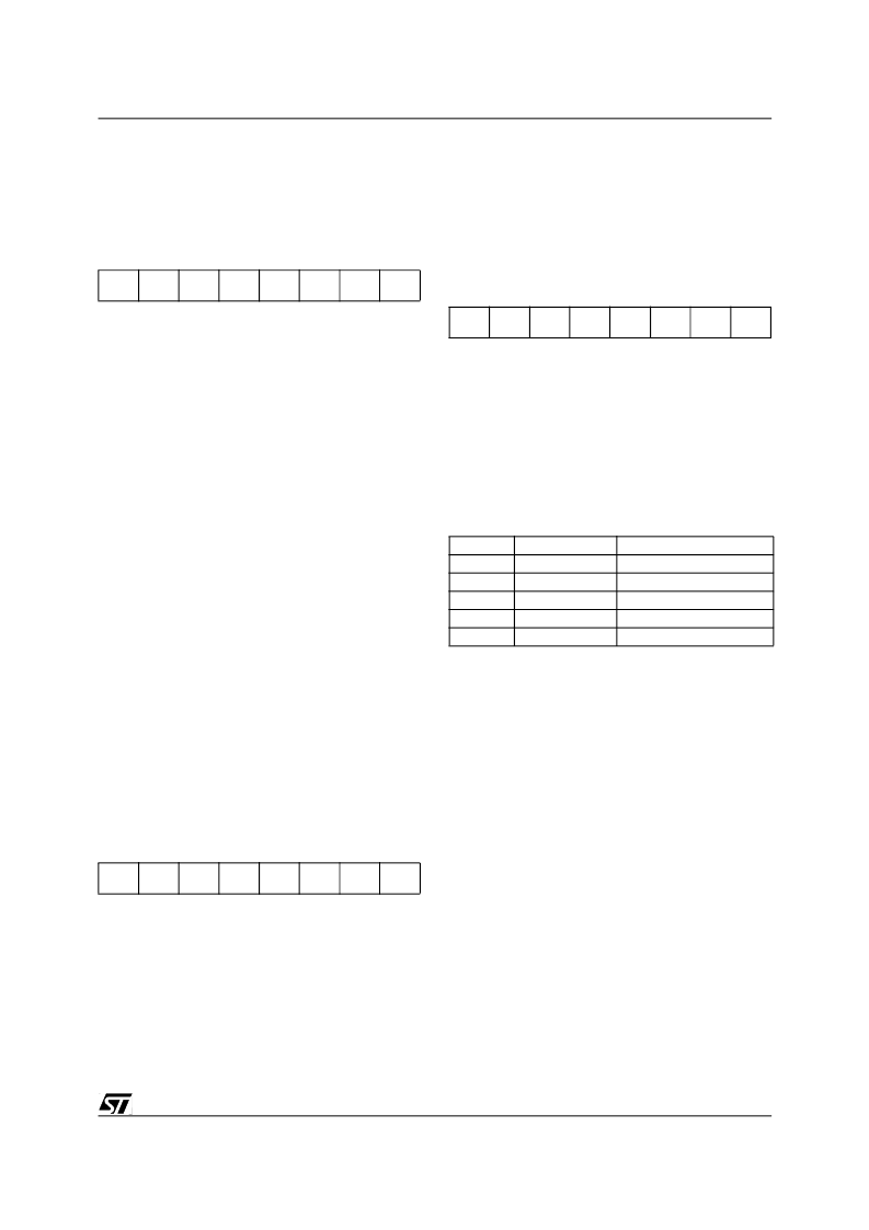
AUTOCLEAR REGISTER (ACR)
R248 - Read/Write
Register Page: 59
Reset Value: 1111 1111 (FFh)
This register behaves exactly as a 9th compare
Register, but its effect is to clear the CRR counter
register, so causing the desired PWM repetition
rate.
The reset condition generates the free running
mode. So, FFh means count by 256.
Bit 7:0 =
AC[7:0]
:
Autoclear Count Value.
When 00 is written to the Compare Register, if the
ACR register = FFh, the PWM output bit is always
set except for the last clock count (255 set and 1
reset; the converse when the output is comple-
mented). If the ACR content is less than FFh, the
PWM output bit is set for a number of clock counts
equal to that content (see Figure 2).
Writing the Compare register constant equal to the
ACR register value causes the output bit to be al-
ways reset (or set if complemented).
Example: If 03h is written to the Compare Regis-
ter, the output bit is reset when the CRR counter
reaches the ACR register value and set when it
reaches the Compare register value (after 4 clock
counts, see
Figure 112.
). The action will be re-
versed if the output is complemented. The PWM
mark/space ratio will remain constant until
changed by software writing a new value in the
ACR register.
COUNTER REGISTER (CRR)
R249 - Read Only
Register Page: 59
Reset Value: 0000 0000 (00h)
This read-only register returns the current counter
value when read.
The 8 bit Counter is initialized to 00h at reset, and
is a free running UP counter.
Bit 7:0 =
CR[7:0]
:
Current Counter Value.
PRESCALER
AND
(PCTL)
R250 - Read/Write
Register Page: 59
Reset Value: 0000 1100 (0Ch)
CONTROL
REGISTER
Bit 7:4 =
PR[3:0]
PWM Prescaler value
.
These bits hold the Prescaler preset value. This is
reloaded into the 4-bit prescaler whenever the
prescaler (DOWN Counter) reaches the value 0,
so determining the 8-bit Counter count frequency.
The value 0 corresponds to the maximum counter
frequency which is INTCLK/2. The value Fh corre-
sponds to the maximum frequency divided by 16
(INTCLK/32).
The reset condition initializes the Prescaler to the
Maximum Counter frequency.
Bit 3:2 = Reserved. Forced by hardware to “1”
Bit 1 =
CLR
:
Counter Clear.
This bit when set, allows both to clear the counter,
and to reload the prescaler. The effect is also to
clear the PWM output. It returns “0” if read.
Bit 0 =
CE
:
Counter Enable.
This bit enables the counter and the prescaler
when set to “1”. It stops both when reset without
affecting their current value, allowing the count to
be suspended and then restarted by software “on
fly”.
7
0
AC7
AC6
AC5
AC4
AC3
AC2
AC1
AC0
7
0
CR7
CR6
CR5
CR4
CR3
CR2
CR1
CR0
7
0
PR3
PR2
PR1
PR0
1
1
CLR
CE
PR[3:0]
Divider Factor
Frequency
INTCLK/2 (Max.)
INTCLK/4
INTCLK/6
..
INTCLK/32 (Min.)
0
1
2
..
1
2
3
..
Fh
16
相關(guān)PDF資料 |
PDF描述 |
|---|---|
| ST92F120JV1 | 8/16-BIT FLASH MCU FAMILY WITH RAM. EEPROM AND J1850 BLPD |
| ST92F120JV9 | 8/16-BIT FLASH MCU FAMILY WITH RAM. EEPROM AND J1850 BLPD |
| ST92F120V1 | 8/16-BIT FLASH MCU FAMILY WITH RAM. EEPROM AND J1850 BLPD |
| ST92F150JD | ST9 - 8/16-BIT SINGLE VOLTAGE FLASH MCU FAMILY WITH RAM. E3 TM (EMULATED EEPROM). CAN 2.0B AND J1850 BLPD |
| ST92F150JV1 | Microcontroller |
相關(guān)代理商/技術(shù)參數(shù) |
參數(shù)描述 |
|---|---|
| ST92F120-EPB/US | 功能描述:可擦除可編程ROM ST9 可擦除可編程ROM PROG RoHS:否 制造商:Maxim Integrated 類型: 存儲容量:1024 bit 組織:1 K x 1 接口類型: 工作電流:5 uA 編程電壓: 工作電源電壓:2.8 V to 6 V 最大工作溫度:+ 85 C 安裝風(fēng)格:Through Hole 封裝 / 箱體:TO-92 |
| ST92F120V1Q7 | 功能描述:8位微控制器 -MCU Flash 128K SPI/I2C RoHS:否 制造商:Silicon Labs 核心:8051 處理器系列:C8051F39x 數(shù)據(jù)總線寬度:8 bit 最大時鐘頻率:50 MHz 程序存儲器大小:16 KB 數(shù)據(jù) RAM 大小:1 KB 片上 ADC:Yes 工作電源電壓:1.8 V to 3.6 V 工作溫度范圍:- 40 C to + 105 C 封裝 / 箱體:QFN-20 安裝風(fēng)格:SMD/SMT |
| ST92F120V9Q7 | 功能描述:8位微控制器 -MCU RO 511-ST92F150CV1QB RoHS:否 制造商:Silicon Labs 核心:8051 處理器系列:C8051F39x 數(shù)據(jù)總線寬度:8 bit 最大時鐘頻率:50 MHz 程序存儲器大小:16 KB 數(shù)據(jù) RAM 大小:1 KB 片上 ADC:Yes 工作電源電壓:1.8 V to 3.6 V 工作溫度范圍:- 40 C to + 105 C 封裝 / 箱體:QFN-20 安裝風(fēng)格:SMD/SMT |
| ST92F124R9TB | 功能描述:8位微控制器 -MCU Flash 64K SCI/SPI/I2 RoHS:否 制造商:Silicon Labs 核心:8051 處理器系列:C8051F39x 數(shù)據(jù)總線寬度:8 bit 最大時鐘頻率:50 MHz 程序存儲器大小:16 KB 數(shù)據(jù) RAM 大小:1 KB 片上 ADC:Yes 工作電源電壓:1.8 V to 3.6 V 工作溫度范圍:- 40 C to + 105 C 封裝 / 箱體:QFN-20 安裝風(fēng)格:SMD/SMT |
| ST92F124V1QB | 功能描述:8位微控制器 -MCU Flash 128K 2SCI/SPI RoHS:否 制造商:Silicon Labs 核心:8051 處理器系列:C8051F39x 數(shù)據(jù)總線寬度:8 bit 最大時鐘頻率:50 MHz 程序存儲器大小:16 KB 數(shù)據(jù) RAM 大小:1 KB 片上 ADC:Yes 工作電源電壓:1.8 V to 3.6 V 工作溫度范圍:- 40 C to + 105 C 封裝 / 箱體:QFN-20 安裝風(fēng)格:SMD/SMT |
發(fā)布緊急采購,3分鐘左右您將得到回復(fù)。