- 您現(xiàn)在的位置:買賣IC網(wǎng) > PDF目錄372313 > ST901T (意法半導(dǎo)體) HIGH VOLTAGE IGNITION COIL DRIVER NPN POWER DARLINGTON PDF資料下載
參數(shù)資料
| 型號(hào): | ST901T |
| 廠商: | 意法半導(dǎo)體 |
| 英文描述: | HIGH VOLTAGE IGNITION COIL DRIVER NPN POWER DARLINGTON |
| 中文描述: | 高壓點(diǎn)火線圈驅(qū)動(dòng)達(dá)林頓NPN電源 |
| 文件頁(yè)數(shù): | 37/199頁(yè) |
| 文件大小: | 2813K |
| 代理商: | ST901T |
第1頁(yè)第2頁(yè)第3頁(yè)第4頁(yè)第5頁(yè)第6頁(yè)第7頁(yè)第8頁(yè)第9頁(yè)第10頁(yè)第11頁(yè)第12頁(yè)第13頁(yè)第14頁(yè)第15頁(yè)第16頁(yè)第17頁(yè)第18頁(yè)第19頁(yè)第20頁(yè)第21頁(yè)第22頁(yè)第23頁(yè)第24頁(yè)第25頁(yè)第26頁(yè)第27頁(yè)第28頁(yè)第29頁(yè)第30頁(yè)第31頁(yè)第32頁(yè)第33頁(yè)第34頁(yè)第35頁(yè)第36頁(yè)當(dāng)前第37頁(yè)第38頁(yè)第39頁(yè)第40頁(yè)第41頁(yè)第42頁(yè)第43頁(yè)第44頁(yè)第45頁(yè)第46頁(yè)第47頁(yè)第48頁(yè)第49頁(yè)第50頁(yè)第51頁(yè)第52頁(yè)第53頁(yè)第54頁(yè)第55頁(yè)第56頁(yè)第57頁(yè)第58頁(yè)第59頁(yè)第60頁(yè)第61頁(yè)第62頁(yè)第63頁(yè)第64頁(yè)第65頁(yè)第66頁(yè)第67頁(yè)第68頁(yè)第69頁(yè)第70頁(yè)第71頁(yè)第72頁(yè)第73頁(yè)第74頁(yè)第75頁(yè)第76頁(yè)第77頁(yè)第78頁(yè)第79頁(yè)第80頁(yè)第81頁(yè)第82頁(yè)第83頁(yè)第84頁(yè)第85頁(yè)第86頁(yè)第87頁(yè)第88頁(yè)第89頁(yè)第90頁(yè)第91頁(yè)第92頁(yè)第93頁(yè)第94頁(yè)第95頁(yè)第96頁(yè)第97頁(yè)第98頁(yè)第99頁(yè)第100頁(yè)第101頁(yè)第102頁(yè)第103頁(yè)第104頁(yè)第105頁(yè)第106頁(yè)第107頁(yè)第108頁(yè)第109頁(yè)第110頁(yè)第111頁(yè)第112頁(yè)第113頁(yè)第114頁(yè)第115頁(yè)第116頁(yè)第117頁(yè)第118頁(yè)第119頁(yè)第120頁(yè)第121頁(yè)第122頁(yè)第123頁(yè)第124頁(yè)第125頁(yè)第126頁(yè)第127頁(yè)第128頁(yè)第129頁(yè)第130頁(yè)第131頁(yè)第132頁(yè)第133頁(yè)第134頁(yè)第135頁(yè)第136頁(yè)第137頁(yè)第138頁(yè)第139頁(yè)第140頁(yè)第141頁(yè)第142頁(yè)第143頁(yè)第144頁(yè)第145頁(yè)第146頁(yè)第147頁(yè)第148頁(yè)第149頁(yè)第150頁(yè)第151頁(yè)第152頁(yè)第153頁(yè)第154頁(yè)第155頁(yè)第156頁(yè)第157頁(yè)第158頁(yè)第159頁(yè)第160頁(yè)第161頁(yè)第162頁(yè)第163頁(yè)第164頁(yè)第165頁(yè)第166頁(yè)第167頁(yè)第168頁(yè)第169頁(yè)第170頁(yè)第171頁(yè)第172頁(yè)第173頁(yè)第174頁(yè)第175頁(yè)第176頁(yè)第177頁(yè)第178頁(yè)第179頁(yè)第180頁(yè)第181頁(yè)第182頁(yè)第183頁(yè)第184頁(yè)第185頁(yè)第186頁(yè)第187頁(yè)第188頁(yè)第189頁(yè)第190頁(yè)第191頁(yè)第192頁(yè)第193頁(yè)第194頁(yè)第195頁(yè)第196頁(yè)第197頁(yè)第198頁(yè)第199頁(yè)
37/199
ST90158 - REGISTER AND MEMORY MAP
3 REGISTER AND MEMORY MAP
3.1 MEMORY CONFIGURATION
The Program memory space of the ST90135/158,
0/24/32/48/64/K bytes of directly addressable on-
chip memory, is fully available to the user.
The first 256 memory locations from address 0 to
FFh hold the Reset Vector, the Top-Level (Pseudo
Non-Maskable) interrupt, the Divide by Zero Trap
Routine vector and, optionally, the interrupt vector
table for use with the on-chip peripherals and the
external interrupt sources. Apart from this case no
other part of the Program memory has a predeter-
mined function except segment 21h which is re-
served for use by STMicroelectronics.
3.2 EPROM PROGRAMMING
The 65536 bytes of EPROM memory of the
ST90E158 may be programmed by using the
EPROM Programming Boards (EPB) available
from STMicroelectronics or gang programmers
available from third party.
EPROM Erasing
The EPROM of the windowed package of the
ST90E158 may be erased by exposure to Ultra-Vi-
olet light.
The erasure characteristic of the ST90E158 is
such that erasure begins when the memory is ex-
posed to light with a wave lengths shorter than ap-
proximately 4000. It should be noted that sunlight
and some types of fluorescent lamps have wave-
lengths in the range 3000-4000. It is thus recom-
mended that the window of the ST90E158 packag-
es be covered by an opaque label to prevent unin-
tentional erasure problems when testing the appli-
cation in such an environment.
The recommended erasure procedure of the
EPROM is the exposure to short wave ultraviolet
light which have a wave-length 2537. The inte-
grated dose (i.e. U.V. intensity x exposure time) for
erasure should be a minimum of 15W-sec/cm2.
The erasure time with this dosage is approximate-
ly 30 minutes using an ultraviolet lamp with
12000mW/cm2 power rating. The ST90E158
should be placed within 2.5cm (1 inch) of the lamp
tubes during erasure.
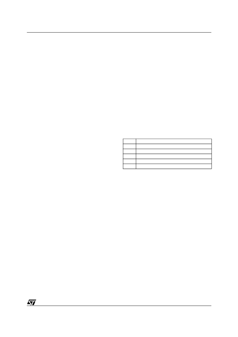
Table 5. First 6 Bytes of Program Space
0
1
2
3
4
5
Address high of Power on Reset routine
Address low of Power on Reset routine
Address high of Divide by zero trap Subroutine
Address low of Divide by zero trap Subroutine
Address high of Top Level Interrupt routine
Address low of Top Level Interrupt routine
9
相關(guān)PDF資料 |
PDF描述 |
|---|---|
| ST9291J7B1 | Microcontroller |
| ST9291N2B1 | Microcontroller |
| ST9291N3B1 | Microcontroller |
| ST9291N4B1 | Microcontroller |
| ST9291N5B1 | Microcontroller |
相關(guān)代理商/技術(shù)參數(shù) |
參數(shù)描述 |
|---|---|
| ST901T_05 | 制造商:STMICROELECTRONICS 制造商全稱:STMicroelectronics 功能描述:HIGH VOLTAGE IGNITION COIL DRIVER NPN POWER TRANSISTOR |
| ST901TFP | 功能描述:兩極晶體管 - BJT PWR BIP/S.SIGNAL RoHS:否 制造商:STMicroelectronics 配置: 晶體管極性:PNP 集電極—基極電壓 VCBO: 集電極—發(fā)射極最大電壓 VCEO:- 40 V 發(fā)射極 - 基極電壓 VEBO:- 6 V 集電極—射極飽和電壓: 最大直流電集電極電流: 增益帶寬產(chǎn)品fT: 直流集電極/Base Gain hfe Min:100 A 最大工作溫度: 安裝風(fēng)格:SMD/SMT 封裝 / 箱體:PowerFLAT 2 x 2 |
| ST9020B1 | 制造商:未知廠家 制造商全稱:未知廠家 功能描述:8-Bit Microcontroller |
| ST9020B6 | 制造商:未知廠家 制造商全稱:未知廠家 功能描述:8-Bit Microcontroller |
| ST9027 | 制造商:STMICROELECTRONICS 制造商全稱:STMicroelectronics 功能描述:16K PROM / 256 RAM HCMOS MCUS |
發(fā)布緊急采購(gòu),3分鐘左右您將得到回復(fù)。