- 您現在的位置:買賣IC網 > PDF目錄98144 > ST72141K2B3/XXX (STMICROELECTRONICS) 8-BIT, MROM, 8 MHz, MICROCONTROLLER, PDIP32 PDF資料下載
參數資料
| 型號: | ST72141K2B3/XXX |
| 廠商: | STMICROELECTRONICS |
| 元件分類: | 微控制器/微處理器 |
| 英文描述: | 8-BIT, MROM, 8 MHz, MICROCONTROLLER, PDIP32 |
| 封裝: | 0.400 INCH, PLASTIC, SDIP-32 |
| 文件頁數: | 86/133頁 |
| 文件大小: | 2615K |
| 代理商: | ST72141K2B3/XXX |
第1頁第2頁第3頁第4頁第5頁第6頁第7頁第8頁第9頁第10頁第11頁第12頁第13頁第14頁第15頁第16頁第17頁第18頁第19頁第20頁第21頁第22頁第23頁第24頁第25頁第26頁第27頁第28頁第29頁第30頁第31頁第32頁第33頁第34頁第35頁第36頁第37頁第38頁第39頁第40頁第41頁第42頁第43頁第44頁第45頁第46頁第47頁第48頁第49頁第50頁第51頁第52頁第53頁第54頁第55頁第56頁第57頁第58頁第59頁第60頁第61頁第62頁第63頁第64頁第65頁第66頁第67頁第68頁第69頁第70頁第71頁第72頁第73頁第74頁第75頁第76頁第77頁第78頁第79頁第80頁第81頁第82頁第83頁第84頁第85頁當前第86頁第87頁第88頁第89頁第90頁第91頁第92頁第93頁第94頁第95頁第96頁第97頁第98頁第99頁第100頁第101頁第102頁第103頁第104頁第105頁第106頁第107頁第108頁第109頁第110頁第111頁第112頁第113頁第114頁第115頁第116頁第117頁第118頁第119頁第120頁第121頁第122頁第123頁第124頁第125頁第126頁第127頁第128頁第129頁第130頁第131頁第132頁第133頁
Obsolete
Product(s)
- Obsolete
Product(s)
ST72141K2
56/133
MOTOR CONTROLLER (Cont’d)
Autoswitched Mode
In this mode the MCOMP register content is auto-
matically computed in real time as described be-
low and in Figure 35. This register is READ ONLY.
The C event has no effect on the contents of the
MTIM timer.
When a Z event occurs the MTIM timer value is
captured in the MZREG register, the previous cap-
tured value is shifted into the MZPRV register and
the MTIM timer is reset. See Figure 26.
One of these two registers (depending on the DCB
bit in the MCRA register) is multiplied with the con-
tents of the MWGHT register and divided by 32.
The result is loaded in the MCOMP compare reg-
ister, which automatically triggers the next com-
mutation (C event)
Table 19. Multiplier Result
When an overflow occurs during the multiply oper-
ation, FFh is written in the MCOMP register and an
interrupt (O event) is generated if enabled by the
OIM bit in the MIMR register.
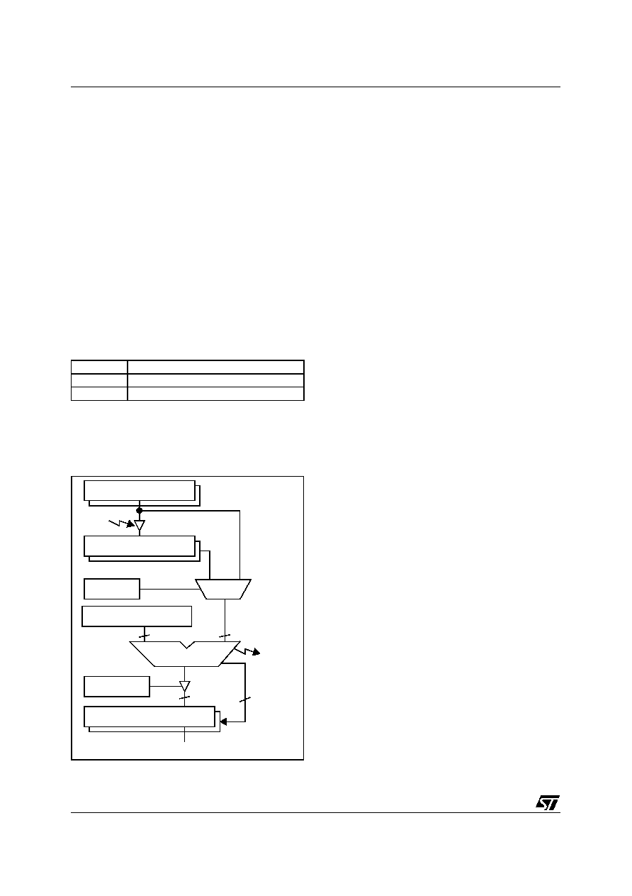
Figure 35. Commutation Processor Block
When the timer reaches this value an RPI interrupt
is generated (timer overflow).
After each shift operation the multiply is recomput-
ed for greater precision.
Using either the MZREG or MZPRV register de-
pends on the motor symmetry and type.
The MWGHT register gives directly the phase shift
between the motor driven voltage and the BEMF.
This parameter generally depends on the motor
and on the speed.
Auto-updated Step Ratio Register: In switched
mode, the MTIM timer is driven by software only
and any prescaler change has to be done by soft-
ware (see Section 8.1.4.2 for more details).
– In autoswitched mode an auto-updated prescal-
er always configures the MTIM timer for best ac-
curacy. Figure 34 shows process of updating the
Step Ratio bits:
– When the MTIM timer value reaches FFh, the pr-
escaler is automatically incremented in order to
slow down the MTIM timer and avoid an over-
flow. To keep consistent values, the MTIM regis-
ter and all the relevant registers are shifted right
(divided by two). The RPI bit in the MISR register
is set and an interrupt is generated (if RIM is set).
– When a Z-event occurs, if the MTIM timer value
is below 55h, the prescaler is automatically dec-
remented in order to speed up the MTIM timer
and keep precision better than 1.2%. The MTIM
register and all the relevant registers are shifted
left (multiplied by two). The RMI bit in the MISR
register is set and an interrupt is generated if RIM
is set.
– If the prescaler contents reach the value 0, it can
no longer be automatically decremented, the
MTC continues working with the same prescaler
value, i.e. with a lower accuracy. No RMI in-
terrrupt can be generated.
– If the prescaler contents reach the value 15, it
can no longer be automatically incremented.
When the timer reaches the value FFh, the pres-
caler and all the relevant registers remain un-
changed and no interrupt is generated, the timer
clock is disabled, and its contents stay at FFh
The PWM is still generated and the D and Z de-
tection circuitry still work, enabling the capture of
the maximum timer value.
The automatically updated registers are: MTIM,
MZREG, MZPRV, MCOMP and MDREG. Access
to these registers is summarised in Table 22.
DCB bit
Commutation Delay
0
MCOMP = MWGHT x MZPRV / 32
1
MCOMP = MWGHT x MZREG / 32
MWGHT [an+1]
MZREG [Zn]
§
A x B / 32
MZPRV [Zn-1]
§
3
DCB bit
SWA bit
MCOMP [Cn+1]
§
Z
set
8
n
n-1
O
To
§ = Register updated on R event
generator
interrupt
MCRA Register
相關PDF資料 |
PDF描述 |
|---|---|
| ST72311N4T6/XXX | 8-BIT, MROM, 8 MHz, MICROCONTROLLER, PQFP64 |
| ST72311J2B6/XXX | 8-BIT, MROM, 8 MHz, MICROCONTROLLER, PDIP42 |
| ST72311N2T3/XXX | 8-BIT, MROM, 8 MHz, MICROCONTROLLER, PQFP64 |
| ST72321BAR7T6 | MICROCONTROLLER, QFP64 |
| ST72321BR7T3 | MICROCONTROLLER, QFP64 |
相關代理商/技術參數 |
參數描述 |
|---|---|
| ST72141K2B6 | 制造商:STMICROELECTRONICS 制造商全稱:STMicroelectronics 功能描述:8-BIT MCU WITH ELECTRIC-MOTOR CONTROL, ADC, 16-BIT TIMERS, SPI INTERFACE |
| ST72141K2M1 | 制造商:STMICROELECTRONICS 制造商全稱:STMicroelectronics 功能描述:8-BIT MCU WITH ELECTRIC-MOTOR CONTROL, ADC, 16-BIT TIMERS, SPI INTERFACE |
| ST72141K2M3 | 制造商:STMICROELECTRONICS 制造商全稱:STMicroelectronics 功能描述:8-BIT MCU WITH ELECTRIC-MOTOR CONTROL, ADC, 16-BIT TIMERS, SPI INTERFACE |
| ST72141K2M3/XXX | 制造商:未知廠家 制造商全稱:未知廠家 功能描述:Microcontroller |
| ST72141K2M6 | 制造商:STMICROELECTRONICS 制造商全稱:STMicroelectronics 功能描述:8-BIT MCU WITH ELECTRIC-MOTOR CONTROL, ADC, 16-BIT TIMERS, SPI INTERFACE |
發(fā)布緊急采購,3分鐘左右您將得到回復。