- 您現(xiàn)在的位置:買賣IC網(wǎng) > PDF目錄372309 > ST7066-0B Controller Miscellaneous - Datasheet Reference PDF資料下載
參數(shù)資料
| 型號(hào): | ST7066-0B |
| 英文描述: | Controller Miscellaneous - Datasheet Reference |
| 中文描述: | 控制器雜項(xiàng)-數(shù)據(jù)表參考 |
| 文件頁數(shù): | 5/30頁 |
| 文件大小: | 363K |
| 代理商: | ST7066-0B |
第1頁第2頁第3頁第4頁當(dāng)前第5頁第6頁第7頁第8頁第9頁第10頁第11頁第12頁第13頁第14頁第15頁第16頁第17頁第18頁第19頁第20頁第21頁第22頁第23頁第24頁第25頁第26頁第27頁第28頁第29頁第30頁
ST7066
Pin Functions
NAME
V1.1
1999/12/29
5
NUMBER I/O
INTERFACED WITH
FUNCTION
RS
1
I
MPU
Select registers.
0: Instruction register (for write) Busy flag:
address counter (for read)
1: Data register (for write and read)
Select read or write.
0: Write
1: Read
Starts data read/write.
Four high order bi-directional tristate data bus
pins. Used for data transfer and receive
between the MPU and the ST7066. DB7 can
be used as a busy flag.
Four low order bi-directional tristate data bus
pins. Used for data transfer and receive
between the MPU and the ST7066.
These pins are not used during 4-bit operation.
Clock to latch serial data D sent to the
extension driver
Clock to shift serial data D
Switch signal for converting the liquid crystal
drive waveform to AC
Character pattern data corresponding to each
segment signal
Common signals that are not used are changed
to non-selection waveform. COM9 to COM16
are non-selection waveforms at 1/8 duty factor
and COM12 to COM16 are non-selection
waveforms at 1/11 duty factor.
Segment signals
Power supply for LCD drive
V
CC
- V5 = 11 V (Max)
V
CC
: 2.7V to 5.5V, GND: 0V
When crystal oscillation is performed, a resistor
must be connected externally. When the pin
input is an external clock, it must be input to OSC1.
R/W
1
I
MPU
E
1
I
MPU
DB4 to DB7
4
I/O
MPU
DB0 to DB3
4
I/O
MPU
CL1
1
O
Extension driver
CL2
1
O
Extension driver
M
1
O
Extension driver
D
1
O
Extension driver
COM1 to COM16
16
O
LCD
SEG1 to SEG40
40
O
LCD
V1 to V5
5
-
Power supply
V
CC
, GND
2
-
Power supply
OSC1, OSC2
2
Oscillation
resistor clock
Note:
1. Vcc>=V1>=V2>=V3>=V4>=V5 must be maintained
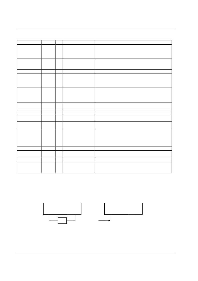
2. Two clock options:
R
OSC1
1
OSC2
1
OSC1
1
OSC2
1
Clock
input
R=91K
(Vcc=5V)
R=75K
相關(guān)PDF資料 |
PDF描述 |
|---|---|
| ST72311N5B6 | 8-BIT MICROCONTROLLER |
| ST72311N6B6 | 8-BIT MICROCONTROLLER |
| ST72311R4Q6 | 8-BIT MICROCONTROLLER |
| ST72311R5Q6 | 8-BIT MICROCONTROLLER |
| ST72311R6Q6 | 8-BIT MICROCONTROLLER |
相關(guān)代理商/技術(shù)參數(shù) |
參數(shù)描述 |
|---|---|
| ST7066U | 制造商:SITRONIX 制造商全稱:SITRONIX 功能描述:Dot Matrix LCD Controller/Driver |
| ST7070 | 制造商:SITRONIX 制造商全稱:SITRONIX 功能描述:Dot Matrix LCD Controller/Driver |
| ST7078 | 制造商:Pulse 功能描述:CMC - Bulk |
| ST7078001 | 制造商:PULSE 功能描述:* |
| ST7078-001 | 制造商:Pulse 功能描述:CMC, SEE 23Z104SM-T FOR STD PART INSTEAD - Bulk |
發(fā)布緊急采購(gòu),3分鐘左右您將得到回復(fù)。