- 您現(xiàn)在的位置:買賣IC網(wǎng) > PDF目錄98083 > SM5L3 (SHARP ELECTRONICS CORP) 4-BIT, MROM, MICROCONTROLLER, PQFP80 PDF資料下載
參數(shù)資料
| 型號: | SM5L3 |
| 廠商: | SHARP ELECTRONICS CORP |
| 元件分類: | 微控制器/微處理器 |
| 英文描述: | 4-BIT, MROM, MICROCONTROLLER, PQFP80 |
| 封裝: | 14 X 20 MM, PLASTIC, QFP-80 |
| 文件頁數(shù): | 10/27頁 |
| 文件大小: | 164K |
| 代理商: | SM5L3 |
第1頁第2頁第3頁第4頁第5頁第6頁第7頁第8頁第9頁當前第10頁第11頁第12頁第13頁第14頁第15頁第16頁第17頁第18頁第19頁第20頁第21頁第22頁第23頁第24頁第25頁第26頁第27頁

SM5L1/SM5L2/SM5L3
4-Bit Single Chip Microcomputers
18
Microcomputer Data Sheet
Standby Function
A standby function is available which temporarily
stops program execution to conserve power consump-
tion. The state during which a program is in execution
is called the operation mode and the state during which
the execution is temporarily stopped is called the
standby mode.
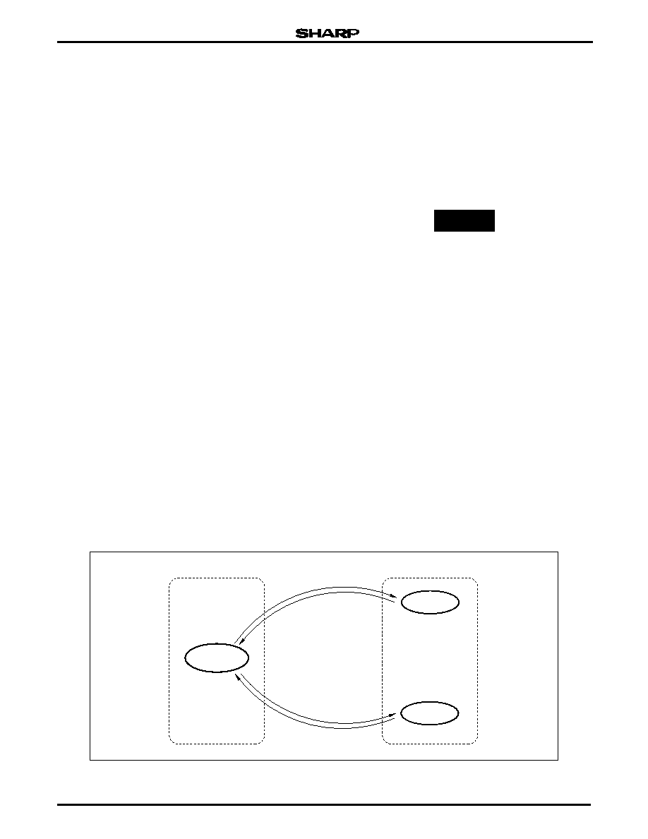
The standby mode further contains two modes, the
stop mode and the halt mode. The stop mode stops the
system section. In the stop mode, the display (LCD) is
blanked. And the response speed of LCD returning to
the display state (the operation) drops slightly.
The halt mode stops only the system clock genera-
tor circuit, the state of the LCD is retained. This mode
is used to activate the system immediately after a con-
dition causes a release to the operation mode.
To enter the standby mode, select either stop mode
or halt mode, whichever is appropriate. See Figure 23.
During the standby mode, the contents of the RAM
and C flag are retained. The contents of the flags, regis-
ters and output latches shown below are also retained.
Flags
– IFA flag
– IFD flag
– IME flag
Registers
– ACC
– X register
– BM, BL register
– SP
– SR
Output latch registers
– P0 register
– P1 register
– P2 register
A release from the standby mode to the operation
mode is performed by a reset port input, an interrupt
from the nonmaskable INTA and divider. A maskable
interrupt request cannot become a factor in releasing
back to the operation mode. The mask setting is per-
formed with RE register, see Table 1.
TRANSITION FROM THE OPERATION MODE TO
THE STANDBY MODE
The HALT instruction is executed to set the halt
mode and the STOP instruction is executed to set the
stop mode.
Since the interrupt is used to release from the standby
mode, the mode does not transfer to the standby mode
if any of the following conditions are satisfied during exe-
cution of the STOP or HALT instruction.
RE0 is set and the INTA level is HIGH.
RE2 is set and the IFD flag is set.
If any of the conditions above are satisfied, the mode
does not transfer to the standby mode even if the
STOP or HALT instruction is executed and the instruc-
tion at the address following that of the STOP or HALT
instruction is executed. Therefore, place the JUMP
instruction which specified step ‘0’ on page 3 to the
location at the address following that of the STOP or
HALT instruction.
When all of P10 to P13 levels are HIGH, the SM5Lx is pro-
grammed to release the standby mode and enter a normally
hardware reset operation (mask option).
CAUTION
Figure 23. Operation Shift of Program
NORMAL
OPERATION
HALT MODE
RELEASE EVENT
RUN STOP
COMMAND
STOP MODE
RELEASE EVENT
RUN HALT
COMMAND
HALT MODE
STOP MODE
STANDBY MODE
OPERATION MODE
5L1-23
相關PDF資料 |
PDF描述 |
|---|---|
| SM802104UMG | 212.5 MHz, OTHER CLOCK GENERATOR, QCC24 |
| SM802105UMG | 312.5 MHz, OTHER CLOCK GENERATOR, QCC24 |
| SM802108UMG | 156.25 MHz, OTHER CLOCK GENERATOR, QCC24 |
| SMC34C90 | PCI BUS CONTROLLER, PBGA256 |
| SMC6247 | 4-BIT, MROM, 1 MHz, MICROCONTROLLER, PQFP160 |
相關代理商/技術(shù)參數(shù) |
參數(shù)描述 |
|---|---|
| SM5LS | 制造商:Potter & Brumfield 功能描述:RELAY SPDT .25A 5000 ohm special |
| SM5LS-5000 | 制造商:P&B 功能描述: 制造商:TE Connectivity 功能描述: |
| SM5M2 | 制造商:SHARP 制造商全稱:Sharp Electrionic Components 功能描述:4-Bit Single-Chip Microcomputer(LCD Driver) |
| SM-5R1000FE6 | 功能描述:RES 0.1 OHM 1% 4W 制造商:vishay dale 系列:SM 包裝:剪切帶(CT) 零件狀態(tài):Digi-Key 停止供應 電阻值:100 mOhms 容差:±1% 功率(W):4W 成分:繞線 特性:- 溫度系數(shù):- 工作溫度:-55°C ~ 275°C 封裝/外殼:8230 J 形引線 供應商器件封裝:SM-5 大小/尺寸:0.820" 長 x 0.295" 寬(20.83mm x 7.49mm) 高度 - 安裝(最大值):0.305"(7.75mm) 端子數(shù):2 故障率:- 標準包裝:1 |
| SM-5R5000FE6 | 功能描述:RES 0.5 OHM 1% 4W 制造商:vishay dale 系列:SM 包裝:剪切帶(CT) 零件狀態(tài):Digi-Key 停止供應 電阻值:500 mOhms 容差:±1% 功率(W):4W 成分:繞線 特性:- 溫度系數(shù):- 工作溫度:-55°C ~ 275°C 封裝/外殼:8230 J 形引線 供應商器件封裝:SM-5 大小/尺寸:0.820" 長 x 0.295" 寬(20.83mm x 7.49mm) 高度 - 安裝(最大值):0.305"(7.75mm) 端子數(shù):2 故障率:- 標準包裝:1 |
發(fā)布緊急采購,3分鐘左右您將得到回復。