- 您現(xiàn)在的位置:買賣IC網(wǎng) > PDF目錄372109 > SAA3500H (NXP SEMICONDUCTORS) Digital audio broadcast channel decoder PDF資料下載
參數(shù)資料
| 型號(hào): | SAA3500H |
| 廠商: | NXP SEMICONDUCTORS |
| 元件分類: | 消費(fèi)家電 |
| 英文描述: | Digital audio broadcast channel decoder |
| 中文描述: | SPECIALTY CONSUMER CIRCUIT, PQFP100 |
| 封裝: | 14 X 20 MM, 2.70 MM HEIGHT, PLASTIC, MO-112, SOT-317-1, QFP-100 |
| 文件頁數(shù): | 11/32頁 |
| 文件大小: | 156K |
| 代理商: | SAA3500H |
第1頁第2頁第3頁第4頁第5頁第6頁第7頁第8頁第9頁第10頁當(dāng)前第11頁第12頁第13頁第14頁第15頁第16頁第17頁第18頁第19頁第20頁第21頁第22頁第23頁第24頁第25頁第26頁第27頁第28頁第29頁第30頁第31頁第32頁
2000 Jun 14
11
Philips Semiconductors
Preliminary specification
Digital audio broadcast channel decoder
SAA3500H
In the CIR output mode the channel impulse response is clocked out in a burst of N (unsigned) samples at 64 kHz each
frame after CIR processing (bit SyncBusy = logic 0). The edges of the frame trigger signal (OIQ) allow to trigger a CIR
display either at the start of the symbol or at the start of the symbol guard. In the latter case the CIR peak for a Gaussian
channel will be at the left of the display.
9.4
Serial output interface
The serial output interface is intended for transferring up to three sub-channels to the source decoder(s) with a total
maximum bit rate of 384 kbit/s. The sub-channels for these outputs should be selected with the appropriate I
2
C or L3
commands. The output clock is 384 kHz. Each sub-channel has its own serial data and data valid line, but the clock is
common. Serial output data shall be latched on the rising edge of SOC.
9.5
Simple full capacity output
This interface provides serial access to all the Viterbi decoder output bits without any formatting. Transmission framing
is indicated by the CFIC window, which can also be used to separate the FIC data (CFIC = HIGH) from the Main Service
Channel (MSC) data (CFIC = LOW). The bit CFICMode can be used to signal on CFIC the beginning of the selected
sub-channels (CFICMode = logic 0). The clock is a 3072 kHz burst clock, activated for each new output bit.
Accompanied with the data is the error flag, obtained by re-encoding the Viterbi output bits and comparison with the
corresponding Viterbi decoder input bits (REF = HIGH for error bit).
9.6
RDI output
For external use a bi-phase modulated output (RDO) is provided, which carries all the FIC and MSC data, formatted
according to the DAB receiver data interface specification “EN 50255” which is based on the IEC 60958 digital audio
interface. Optionally, a clock (6144 kHz) and word select signal (48 kHz) can be provided (instead of SFCO signals).
Transmitter Identification Information (TII) is not signalled on this RDI. The FIC however is always signalled, with the
Cyclic Redundancy Check (CRC) performed and the Error Check Field containing the resulting CRC (normally 0).
Selected sub-channels will be directed to the RDI interface in the extended capacity mode (22 bits for MSC), but the
number of RDI frames and the reliability are not signalled (i.e., set to all logic 0s and all logic 1s, respectively).
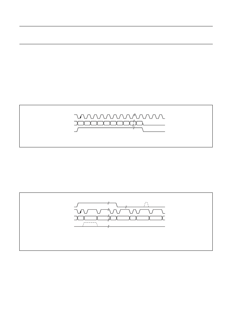
SOC
SOV
SOD
Fig.8 DAB3 serial output.
RDC
CFIC
SFCO
REF
CFICMode = 0
Fig.9 Simple full capacity output (CFICMode = logic 1).
相關(guān)PDF資料 |
PDF描述 |
|---|---|
| SAA4700T | VPS dataline processor |
| SAA4700 | VPS dataline processor |
| SAA4945H | LIne MEmory noise Reduction IC LIMERIC |
| SAA4951 | RES 6.49K OHM 1/16W 0.5% 0402SMD |
| SAA4951WP | Memory controller |
相關(guān)代理商/技術(shù)參數(shù) |
參數(shù)描述 |
|---|---|
| SAA35020004 | 制造商:LG Corporation 功能描述:S/W,Firmware |
| SAA35020005 | 制造商:LG Corporation 功能描述:S/W,Firmware |
| SAA35020008 | 制造商:LG Corporation 功能描述:S/W,Firmware |
| SAA35020103 | 制造商:LG Corporation 功能描述:S/W,Firmware |
| SAA35020104 | 制造商:LG Corporation 功能描述:S/W,Firmware |
發(fā)布緊急采購,3分鐘左右您將得到回復(fù)。