- 您現(xiàn)在的位置:買賣IC網(wǎng) > PDF目錄374689 > SA9904BSA (Electronic Theatre Controls, Inc.) Three Phase Power / Energy IC with SPI Interface PDF資料下載
參數(shù)資料
| 型號: | SA9904BSA |
| 廠商: | Electronic Theatre Controls, Inc. |
| 英文描述: | Three Phase Power / Energy IC with SPI Interface |
| 中文描述: | 三相功率/能量芯片,SPI接口 |
| 文件頁數(shù): | 4/12頁 |
| 文件大小: | 106K |
| 代理商: | SA9904BSA |
TheSA9904BisaCMOSmixedsignalAnalog/Digitalintegrated
circuit, which performs the measurement of active power,
reactive power, RMS voltage and mains frequency. The
integrated circuit includes all the required functions for three-
phase power and energy measurement such as oversampling
A/D converters for the voltage and current sense inputs, power
calculationandenergyintegration.
channel2andresistorsR5andR6oncurrentchannel3,define
the current levels into the SA9904B current sense inputs. The
currentsenseinputssaturatesat±25μApeak.ResistorsRsh1,
Rsh2 and Rsh3 are the current transformer termination
resistors. The voltage drop across the termination resistors
should be at least 20mV but not higher than 200mV. The ideal
value should be approximately 100mV at rated conditions.
Valuesforthecurrentsenseinputsarecalculatedasfollows:
R = R = (
/
) x Rsh / 2
1
2
I
16μA
R = R = (I / 16μA
) x Rsh / 2
R = R = (I / 16μA
) x Rsh / 2
5
L
RMS
L
RMS
3
4
L
RMS
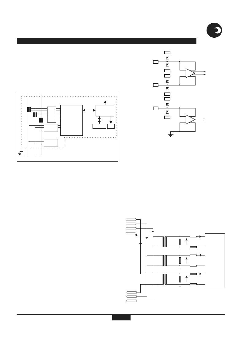
Figure 3:
Typical architecture of an energy meter using the
SA9904B
The SA9904B integrates instantaneous active and reactive
power into 24 bit registers. RMS voltage and frequency are
continuously measured and stored in the respective registers.
ThemainsvoltagezerocrossoverisavailableontheF50output.
The SPI interface of the SA9904B has a tri-state output that
allows connection of more than one metering device on a single
SPIbus.
The input circuitry of the current and voltage sensor inputs is
illustrated in figure 4. These inputs are protected against
electrostatic discharge through clamping diodes. The feedback
loops from the outputs of the amplifiers A and A generate
virtualshortsonthesignalinputs.Exactduplicationsoftheinput
currents are generated for the analog signal processing
circuitry. The current and voltage sense inputs are identical.
Bothinputsaredifferentialcurrentdrivenupto±25μApeak.One
of the voltage sense amplifier input terminals is internally
connected to GND. This is possible because the voltage sense
input is much less sensitive to externally induced parasitic
signalscomparedtothecurrentsenseinputs.
At rated current (I
input currents of 16μA
) the resistor values should be selected for
. Referring to figure 5, the resistors R1
RMS
INPUTSIGNALS
AnalogInputConfiguration
Current SenseInputs(IIN1,IIP1,IIN2,IIP2,IIN3,IIP3)
I
V
MAX
Figure 4: Analog input internal configuration
VOLTAGE
SENSOR
INPUT
IVP
DR-01288
SS
V
CURRENT
SENSOR
INPUTS
IIP
IIN
SS
V
VDD
SS
V
VDD
DD
V
GND
A
V
A
I
Figure 5: Current sense input configuration
C
S
Voltage
Sensing
Power
Supply
SA9904B
Active Energy
Reactive Energy
V
and
Frequency
Measurements
RMS
Calibration LED
Micro-
Controller
LCD
EEPROM
SPI
N
L1
L2 L3
A micro-controller in addition to communicating
with the SA9904B is used to read/write
parameters to the EEPROM, output pulses for
fast calibration and to display the consumed
active and reactive power, Vrms and mains
frequency information. Other parameters such
as Irms, phase angle etc. can be accurately
calculated.
Dr-01643
R1
R2
R3
R4
R5
R6
CH1In
CH2 In
Ch3 In
Rsh1
CT1
CT2
CT3
Rsh2
Rsh3
GND
GND
GND
CH3 Out
CH2 Out
CH1 Out
IIP1
IIN1
IIP2
IIN2
IIP3
IIN3
Neutral
GND
SA9904B
I
MAX
I
MAX
I
MAX
16μA
RMS
16μA
RMS
16μA
RMS
> 20mV
RMS
> 20mV
RMS
> 20mV
RMS
Dr-01644
相關PDF資料 |
PDF描述 |
|---|---|
| SAA-111100 | Single-Mode FC ADAPTOR supplied |
| SAA-111200 | Single-Mode FC ADAPTOR supplied |
| SAA-112200 | Single-Mode FC ADAPTOR supplied |
| SAA-121100 | Single-Mode FC ADAPTOR supplied |
| SAA-121200 | Single-Mode FC ADAPTOR supplied |
相關代理商/技術參數(shù) |
參數(shù)描述 |
|---|---|
| SA993G | 制造商:Cooper Wiring Devices 功能描述: |
| SA9C-CA3D2 | 制造商:IDEC CORPORATION 功能描述:PHOTOELECTRIC SENSOR WITH FIBE |
| SA9C-CA3D5 | 制造商:IDEC CORPORATION 功能描述:PHOTOELECTRIC SENSOR WITH FIBE |
| SA9C-CA4D2 | 制造商:IDEC CORPORATION 功能描述:Reflector Sensor 4-Pin |
| SA9C-CA4D2S | 制造商:IDEC CORPORATION 功能描述:PHOTOELECTRIC SENSOR WITH FIBE |
發(fā)布緊急采購,3分鐘左右您將得到回復。