- 您現(xiàn)在的位置:買賣IC網(wǎng) > PDF目錄385767 > RF2046PCBA-41X (RF Micro Devices, Inc.) GENERAL PURPOSE AMPLIFIER PDF資料下載
參數(shù)資料
| 型號(hào): | RF2046PCBA-41X |
| 廠商: | RF Micro Devices, Inc. |
| 英文描述: | GENERAL PURPOSE AMPLIFIER |
| 中文描述: | 通用放大器 |
| 文件頁數(shù): | 2/8頁 |
| 文件大小: | 113K |
| 代理商: | RF2046PCBA-41X |
4-174
RF2046
Rev A11 050207
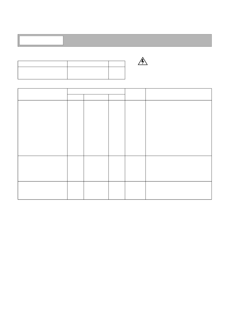
Absolute Maximum Ratings
Parameter
Input RF Power
Operating Ambient Temperature
Storage Temperature
Rating
+13
-40 to +85
-60 to +150
Unit
dBm
°C
°C
Parameter
Specification
Typ.
Unit
Condition
Min.
Max.
Overall
Frequency Range
Gain
T=25°C, V
D
=3.5V, I
CC
=35mA
DC to 3000
22.7
22.1
21.0
19.2
±0.9
2.7
<2.0:1
<1.9:1
+23.5
+10.7
22.8
MHz
dB
dB
dB
dB
dB
dB
Freq=100MHz
Freq=1000MHz
Freq=2000MHz
Freq=3000MHz
100MHz to 2000MHz
Freq=2000MHz
In a 50
Ω
system, DC to 3000MHz
In a 50
Ω
system, DC to 3000MHz
Freq=2000MHz±100kHz, P
TONE
=-18dBm
Freq=2000MHz
Freq=2000MHz
I
CC
=35mA, P
DISS
=116mW (See Note 1.)
18
Gain Flatness
Noise Figure
Input VSWR
Output VSWR
Output IP
3
Output P
1dB
Reverse Isolation
Thermal
Theta
JC
Maximum Measured Junction
Temperature at DC Bias Con-
ditions
Mean Time To Failure (MTTF)
Power Supply
Device Operating Voltage
dBm
dBm
dB
275
117
°C/W
°C
280,000
years
T
AMB
=+85°C
With 22
Ω
bias resistor, T=+25°C
At pin 3 with I
CC
=35mA
At evaluation board connector, I
CC
=35mA
See Note 2.
3.0
3.6
3.5
4.3
4.0
4.6
35
V
V
Operating Current
NOTES:
Note 1: The RF2046 must be operated at or below 35mA in order to achieve the thermal performance stated above. Operating at 35mA
will ensure the best possible combination of reliability and electrical performance.
Note 2: Because of process variations from part to part, the current resulting from a fixed bias voltage will vary. As a result, caution
should be used in designing fixed voltage bias circuits to ensure the worst case bias current does not exceed 35mA over all intended
operating conditions.
mA
Caution!
ESD sensitive device.
RF Micro Devices believes the furnished information is correct and accurate
at the time of this printing. However, RF Micro Devices reserves the right to
make changes to its products without notice. RF Micro Devices does not
assume responsibility for the use of the described product(s).
相關(guān)PDF資料 |
PDF描述 |
|---|---|
| RF2114 | TRI R RECP F FLG SEAL 0-4 |
| RF2114PCBA | MEDIUM POWER LINEAR AMPLIFIER |
| RF2115 | HIGH POWER UHF AMPLIFIER |
| RF2115L | HIGH POWER UHF AMPLIFIER |
| RF2115LPCBA | HIGH POWER UHF AMPLIFIER |
相關(guān)代理商/技術(shù)參數(shù) |
參數(shù)描述 |
|---|---|
| RF2046TR7 | 制造商:RF Micro Devices Inc 功能描述:IC GAIN BLK AMP GEN-PURP 4MICROX |
| RF2047 | 制造商:RFMD 制造商全稱:RF Micro Devices 功能描述:GENERAL PURPOSE AMPLIFIER |
| RF2047-000 | 功能描述:可復(fù)位保險(xiǎn)絲 RoHS:否 制造商:Bourns 電流額定值: 電阻:7.5 Ohms 最大直流電壓: 保持電流:0.1 A 安裝風(fēng)格:SMD/SMT 端接類型:SMD/SMT 跳閘電流:0.6 A 引線間隔: 系列:MF-PSHT 工作溫度范圍:- 40 C to + 125 C |
| RF2047PCBA | 制造商:RFMD 制造商全稱:RF Micro Devices 功能描述:GENERAL PURPOSE AMPLIFIER |
| RF2047TR7 | 制造商:RF Micro Devices Inc 功能描述:IC GAIN BLK AMP GEN-PURP 4MICROX |
發(fā)布緊急采購,3分鐘左右您將得到回復(fù)。