- 您現(xiàn)在的位置:買賣IC網(wǎng) > PDF目錄1966 > QLX4600LIQSR (Intersil)IC EQUALIZER REC 6.25GBPS 46QFN PDF資料下載
參數(shù)資料
| 型號: | QLX4600LIQSR |
| 廠商: | Intersil |
| 文件頁數(shù): | 22/23頁 |
| 文件大?。?/td> | 0K |
| 描述: | IC EQUALIZER REC 6.25GBPS 46QFN |
| 標準包裝: | 100 |
| 系列: | QLx™ |
| 應用: | 銅電纜模塊 |
| 電源電壓: | 1.1 V ~ 1.3 V |
| 封裝/外殼: | 46-WFQFN 裸露焊盤 |
| 供應商設備封裝: | 46-TQFN |
| 包裝: | 帶卷 (TR) |
| 安裝類型: | 表面貼裝 |
8
FN6981.1
November 19, 2009
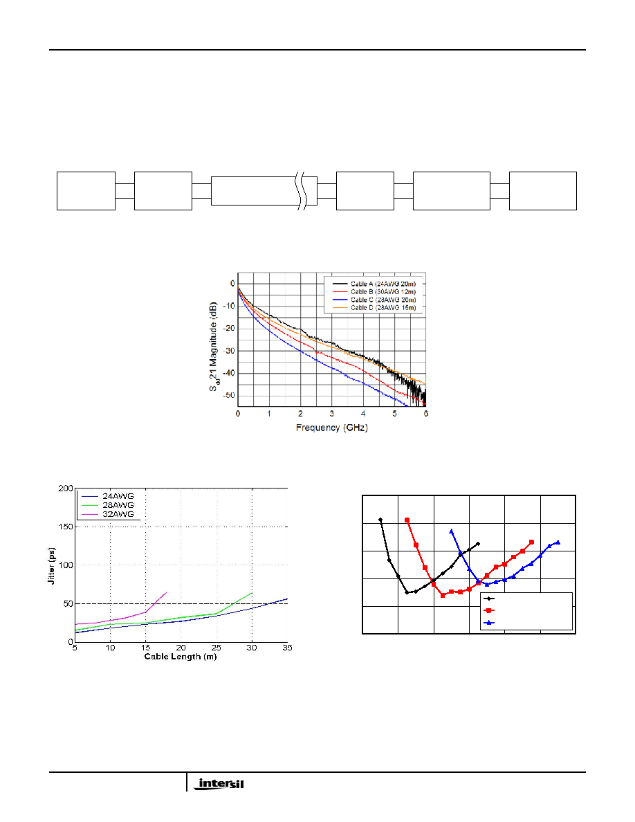
Typical Performance Characteristics
VDD = 1.2V, TA = +25°C, unless otherwise noted. Performance was characterized using the system testbed shown in
Figure 1. Unless otherwise noted, the transmitter generated a non-return-to-zero (NRZ) PRBS-7 sequence at 800mVP-P
(differential) with 10ps of peak-to-peak deterministic jitter. This transmit signal was launched into twin-axial cable test
channels of varying gauges and lengths. The loss characteristics of these test channels are plotted as a function of
frequency in Figure 2. The received signal at the output of these test channels was then processed by the QLx4600-SL30
before being passed to a receiver. Eye diagram measurements were made with 4000 waveform acquisitions and include
random jitter.
FIGURE 1. DEVICE CHARACTERIZATION TEST SETUP
FIGURE 2. TWIN-AXIAL CABLE LOSS AS A FUNCTION OF FREQUENCY FOR VARIOUS TEST CHANNELS
FIGURE 3A. JITTER vs CABLE LENGTH, 5Gb/s
FIGURE 3B. JITTER vs BOOST SETTING, 5Gb/s
FIGURE 3. JITTER VS CABLE LENGTH AND JITTER VS BOOST SETTING AT 5 GBPS
Pattern
Generator
SMA
Adapter
Card
100O Twin-Axial
Cable
SMA
Adapter
Card
QLx4600-SL30
Eval Board
Oscilloscope
Ω
TEST CHANNEL LOSS CHARACTERISTICS
0
0.1
0.2
0.3
0.4
0.5
4
8
12
16
20
24
28
Boost Setting
J
itte
r(
U
I)
Cable A (24AWG 20m)
Cable B (30AWG 12m)
Cable C (28AWG 20m)
QLx4600-SL30
相關PDF資料 |
PDF描述 |
|---|---|
| QLX4600SIQSR | IC EQUALIZER REC 6.25GBPS 46QFN |
| R5F100GEAFB#V0 | MCU 16BIT 64KB FLASH 48LQFP |
| R5F2135CMNFP#V0 | IC MICROCONTROLLER |
| R5F562N8ADBG#U0 | MCU 32BIT FLASH 512KROM 176LFBGA |
| R5F5630ADDFB#V0 | MCU RX630 768KB FLASH 144-LQFP |
相關代理商/技術參數(shù) |
參數(shù)描述 |
|---|---|
| QLX4600LIQT7 | 功能描述:接口 - 專用 6 GBS QD CH LANE EXTENDER RoHS:否 制造商:Texas Instruments 產(chǎn)品類型:1080p60 Image Sensor Receiver 工作電源電壓:1.8 V 電源電流:89 mA 最大功率耗散: 最大工作溫度:+ 85 C 安裝風格:SMD/SMT 封裝 / 箱體:BGA-59 |
| QLX4600MIBQ15 | 制造商:Intersil Corporation 功能描述:IC LINEAR |
| QLX4600-S30 | 制造商:INTERSIL 制造商全稱:Intersil Corporation 功能描述:Quad Lane Extender |
| QLX4600SIQSR | 功能描述:接口 - 專用 6 GBS QD CH LANE EXTENDER RoHS:否 制造商:Texas Instruments 產(chǎn)品類型:1080p60 Image Sensor Receiver 工作電源電壓:1.8 V 電源電流:89 mA 最大功率耗散: 最大工作溫度:+ 85 C 安裝風格:SMD/SMT 封裝 / 箱體:BGA-59 |
| QLX4600SIQT7 | 功能描述:接口 - 專用 6 GBS QD CH LANE EXTENDER RoHS:否 制造商:Texas Instruments 產(chǎn)品類型:1080p60 Image Sensor Receiver 工作電源電壓:1.8 V 電源電流:89 mA 最大功率耗散: 最大工作溫度:+ 85 C 安裝風格:SMD/SMT 封裝 / 箱體:BGA-59 |
發(fā)布緊急采購,3分鐘左右您將得到回復。