- 您現(xiàn)在的位置:買賣IC網(wǎng) > PDF目錄296863 > PSD4135F1V-12M (意法半導(dǎo)體) Flash In-System-Programmable Peripherals for 16-Bit MCUs PDF資料下載
參數(shù)資料
| 型號: | PSD4135F1V-12M |
| 廠商: | 意法半導(dǎo)體 |
| 英文描述: | Flash In-System-Programmable Peripherals for 16-Bit MCUs |
| 中文描述: | Flash在系統(tǒng)可編程外設(shè)的16位微控制器 |
| 文件頁數(shù): | 55/93頁 |
| 文件大小: | 503K |
| 代理商: | PSD4135F1V-12M |
第1頁第2頁第3頁第4頁第5頁第6頁第7頁第8頁第9頁第10頁第11頁第12頁第13頁第14頁第15頁第16頁第17頁第18頁第19頁第20頁第21頁第22頁第23頁第24頁第25頁第26頁第27頁第28頁第29頁第30頁第31頁第32頁第33頁第34頁第35頁第36頁第37頁第38頁第39頁第40頁第41頁第42頁第43頁第44頁第45頁第46頁第47頁第48頁第49頁第50頁第51頁第52頁第53頁第54頁當(dāng)前第55頁第56頁第57頁第58頁第59頁第60頁第61頁第62頁第63頁第64頁第65頁第66頁第67頁第68頁第69頁第70頁第71頁第72頁第73頁第74頁第75頁第76頁第77頁第78頁第79頁第80頁第81頁第82頁第83頁第84頁第85頁第86頁第87頁第88頁第89頁第90頁第91頁第92頁第93頁
PSD4000 Series
Preliminary Information
56
The
PSD4000
Functional
Blocks
(cont.)
Access
5V VCC,
PLD
Memory
Recovery Time
Typical
Propagation
Access
to Normal
Standby
Mode
Delay
Time
Access
Current
Power Down
Normal tpd
No Access
tLVDV
50 A
(Note 1)
(Note 2)
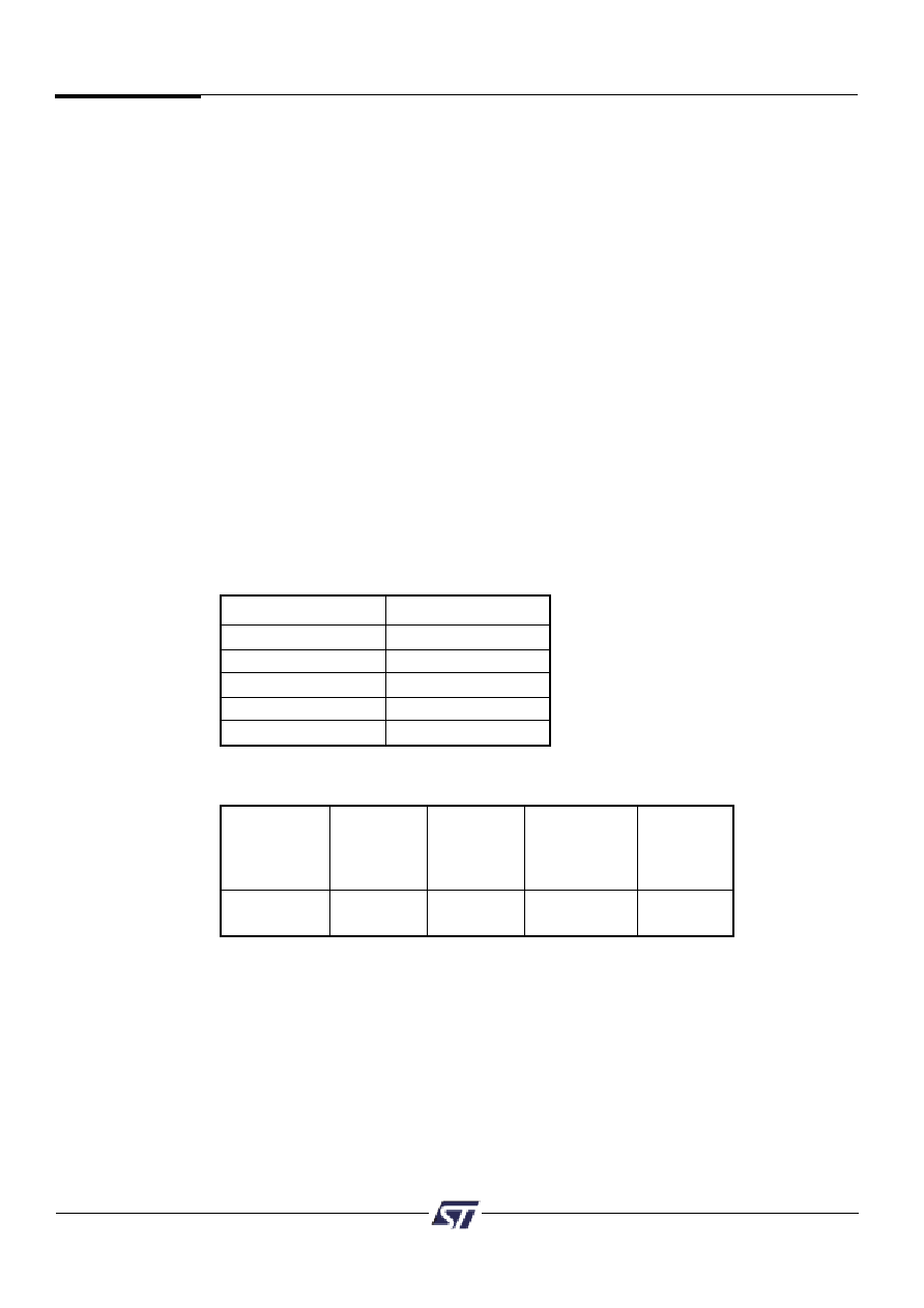
Table 25. PSD4000 Timing and Standby Current During Power
Down Mode
NOTES: 1. Power Down does not affect the operation of the PLD. The PLD operation in this
mode is based only on the Turbo Bit.
2. Typical current consumption assuming no PLD inputs are changing state and
the PLD Turbo bit is off.
Port Function
Pin Level
MCU I/O
No Change
PLD Out
No Change
Address Out
Undefined
Data Port
Three-State
Peripheral I/O
Three-State
Table 24. Power Down Mode’s Effect on
Ports
9.5.1 Automatic Power Down (APD) Unit and Power Down Mode (cont.)
Power Down Mode
By default, if you enable the PSD APD unit, Power Down Mode is automatically enabled.
The device will enter Power Down Mode if the address strobe (ALE/AS) remains inactive
for fifteen CLKIN (pin PD1) clock periods.
The following should be kept in mind when the PSD is in Power Down Mode:
If the address strobe starts pulsing again, the PSD will return to normal operation.
The PSD will also return to normal operation if either the CSI input returns low or the
Reset input returns high.
The MCU address/data bus is blocked from all memories and PLDs.
Various signals can be blocked (prior to Power Down Mode) from entering the PLDs
by setting the appropriate bits in the PMMR registers. The blocked signals include
MCU control signals and the common clock (CLKIN). Note that blocking CLKIN from
the PLDs will not block CLKIN from the APD unit.
All PSD memories enter Standby Mode and are drawing standby current. However,
the PLDs and I/O ports do not go into Standby Mode because you don’t want to
have to wait for the logic and I/O to “wake-up” before their outputs can change. See
Table 24 for Power Down Mode effects on PSD ports.
Typical standby current is 50 A for 5 V parts. This standby current value assumes
that there are no transitions on any PLD input.
相關(guān)PDF資料 |
PDF描述 |
|---|---|
| PSD4235F1V-12B81 | Flash In-System-Programmable Peripherals for 16-Bit MCUs |
| PSD4235F1V-12B81I | Flash In-System-Programmable Peripherals for 16-Bit MCUs |
| PSD4235F1V-12J | Flash In-System-Programmable Peripherals for 16-Bit MCUs |
| PSD4235F1V-12JI | Flash In-System-Programmable Peripherals for 16-Bit MCUs |
| PSD4235F1V-12M | MGrid IDT Rec /OPolKeyLRmp .38AuLF 40Ckt |
相關(guān)代理商/技術(shù)參數(shù) |
參數(shù)描述 |
|---|---|
| PSD4135F1V-12MI | 制造商:STMICROELECTRONICS 制造商全稱:STMicroelectronics 功能描述:Flash In-System-Programmable Peripherals for 16-Bit MCUs |
| PSD4135F1V-12U | 制造商:STMICROELECTRONICS 制造商全稱:STMicroelectronics 功能描述:Flash In-System-Programmable Peripherals for 16-Bit MCUs |
| PSD4135F1V-12UI | 制造商:STMICROELECTRONICS 制造商全稱:STMicroelectronics 功能描述:Flash In-System-Programmable Peripherals for 16-Bit MCUs |
| PSD4135F1V-15B81 | 制造商:STMICROELECTRONICS 制造商全稱:STMicroelectronics 功能描述:Flash In-System-Programmable Peripherals for 16-Bit MCUs |
| PSD4135F1V-15B81I | 制造商:STMICROELECTRONICS 制造商全稱:STMicroelectronics 功能描述:Flash In-System-Programmable Peripherals for 16-Bit MCUs |
發(fā)布緊急采購,3分鐘左右您將得到回復(fù)。