- 您現在的位置:買賣IC網 > PDF目錄383714 > OR2T04A-5M208I (Electronic Theatre Controls, Inc.) Field-Programmable Gate Arrays PDF資料下載
參數資料
| 型號: | OR2T04A-5M208I |
| 廠商: | Electronic Theatre Controls, Inc. |
| 元件分類: | FPGA |
| 英文描述: | Field-Programmable Gate Arrays |
| 中文描述: | 現場可編程門陣列 |
| 文件頁數: | 127/192頁 |
| 文件大?。?/td> | 3148K |
| 代理商: | OR2T04A-5M208I |
第1頁第2頁第3頁第4頁第5頁第6頁第7頁第8頁第9頁第10頁第11頁第12頁第13頁第14頁第15頁第16頁第17頁第18頁第19頁第20頁第21頁第22頁第23頁第24頁第25頁第26頁第27頁第28頁第29頁第30頁第31頁第32頁第33頁第34頁第35頁第36頁第37頁第38頁第39頁第40頁第41頁第42頁第43頁第44頁第45頁第46頁第47頁第48頁第49頁第50頁第51頁第52頁第53頁第54頁第55頁第56頁第57頁第58頁第59頁第60頁第61頁第62頁第63頁第64頁第65頁第66頁第67頁第68頁第69頁第70頁第71頁第72頁第73頁第74頁第75頁第76頁第77頁第78頁第79頁第80頁第81頁第82頁第83頁第84頁第85頁第86頁第87頁第88頁第89頁第90頁第91頁第92頁第93頁第94頁第95頁第96頁第97頁第98頁第99頁第100頁第101頁第102頁第103頁第104頁第105頁第106頁第107頁第108頁第109頁第110頁第111頁第112頁第113頁第114頁第115頁第116頁第117頁第118頁第119頁第120頁第121頁第122頁第123頁第124頁第125頁第126頁當前第127頁第128頁第129頁第130頁第131頁第132頁第133頁第134頁第135頁第136頁第137頁第138頁第139頁第140頁第141頁第142頁第143頁第144頁第145頁第146頁第147頁第148頁第149頁第150頁第151頁第152頁第153頁第154頁第155頁第156頁第157頁第158頁第159頁第160頁第161頁第162頁第163頁第164頁第165頁第166頁第167頁第168頁第169頁第170頁第171頁第172頁第173頁第174頁第175頁第176頁第177頁第178頁第179頁第180頁第181頁第182頁第183頁第184頁第185頁第186頁第187頁第188頁第189頁第190頁第191頁第192頁
Data Sheet
June 1999
ORCA Series 2 FPGAs
Lucent Technologies Inc.
127
Package Thermal Characteristics
(continued)
FPGA Maximum Junction Temperature
Once the power dissipated by the FPGA has been determined (see the Estimating Power Dissipation section), the
maximum junction temperature of the FPGA can be found. This is needed to determine if speed derating of the
device from the 85 °C junction temperature used in all of the delay tables is needed. Using the maximum ambient
temperature, T
Amax
, and the power dissipated by the device, Q (expressed in °C), the maximum junction tempera-
ture is approximated by:
T
Jmax =
T
Amax
+ (Q
Θ
JA
)
Table 29 lists the thermal characteristics for all packages used with the Series 2 FPGAs.
1. Mounted on a sparse copper one-layer test board.
2. Mounted on four-layer JEDEC standard test board with two power/ground planes.
3. With thermal balls connected to board ground plane.
4. Without thermal balls connected to board ground plane.
Note: The
ψ
JC
for the packages listed is <1 °C/W. This implies that virtually all of the heat is dissipated through the board on which the package
is mounted.
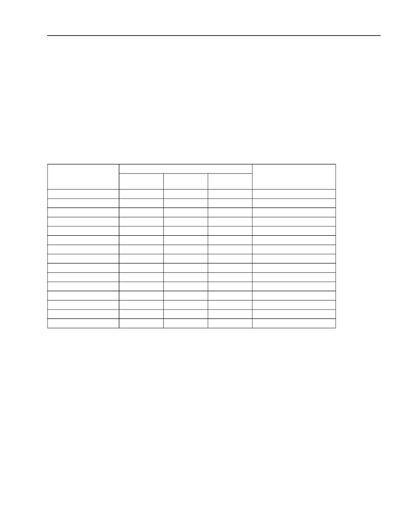
Table 29. Series 2 Plastic Package Thermal Guidelines
Package
Θ
JA
(°C/W)
200 fpm
T
A
= 70 °C max
T
J
= 125 °C max
@ 0 fpm (W)
1.4
1.8—2.0
1.1
2.3
2.1
4.3
2.2
4.2
2.4
2.1
2.0
4.6
2.9
2.1
5.0
0 fpm
500 fpm
84-Pin PLCC
1
100-Pin TQFP
2
144-Pin TQFP
1
160-Pin QFP
2
208-Pin SQFP
2
208-Pin SQFP2
2
240-Pin SQFP
2
240-Pin SQFP2
2
256-Pin PBGA
2, 3
256-Pin PBGA
2, 4
304-Pin SQFP
2
304-Pin SQFP2
2
352-Pin PBGA
2, 3
352-Pin PBGA
2, 4
432-Pin EBGA
2
40.0
35.0
26—23
39.0
21.5
23.0
10.3
22.5
10.0
19.0
22.0
24.0
10.0
16.0
22.0
8.5
—
30.0—27.0
52.0
24.0
26.5
12.8
25.5
13.0
22.5
26.0
27.5
12.0
19.0
25.5
11.0
24.0—21.0
—
20.5
21.0
9.1
21.0
9.0
17.5
20.5
22.5
9.0
15.0
20.5
7.5
Package Coplanarity
The coplanarity limits of the Series 2 series packages
are as follows:
I
TQFP: 3.15 mils
I
PLCC and QFP: 4.0 mils
I
PBGA: 8.0 mils
I
SQFP: 4.0 mils (240 and 304 only)
3.15 mils (all other sizes)
I
SQFP2: 3.15 mils
I
EBGA: 8.0 mils
Package Parasitics
The electrical performance of an IC package, such as
signal quality and noise sensitivity, is directly affected
by the package parasitics. Table 30 lists eight parasitics
associated with the ORCA packages. These parasitics
represent the contributions of all components of a
package, which include the bond wires, all internal
package routing, and the external leads.
Four inductances in nH are listed: L
SW
and L
SL,
the
self-inductance of the lead; and L
MW
and L
ML
, the
mutual inductance to the nearest neighbor lead.
相關PDF資料 |
PDF描述 |
|---|---|
| OR2T04A-5M84 | Field-Programmable Gate Arrays |
| OR2T04A-5M84I | Field-Programmable Gate Arrays |
| OR2T04A-5PS208 | Field-Programmable Gate Arrays |
| OR2T04A-5PS208I | Field-Programmable Gate Arrays |
| OR2T04A-5PS84 | Field-Programmable Gate Arrays |
相關代理商/技術參數 |
參數描述 |
|---|---|
| OR2T04A-5M84 | 制造商:未知廠家 制造商全稱:未知廠家 功能描述:Field-Programmable Gate Arrays |
| OR2T04A-5M84I | 制造商:未知廠家 制造商全稱:未知廠家 功能描述:Field-Programmable Gate Arrays |
| OR2T04A-5PS100 | 制造商:未知廠家 制造商全稱:未知廠家 功能描述:Field-Programmable Gate Arrays |
| OR2T04A-5PS100I | 制造商:未知廠家 制造商全稱:未知廠家 功能描述:Field-Programmable Gate Arrays |
| OR2T04A-5PS144 | 制造商:未知廠家 制造商全稱:未知廠家 功能描述:Field-Programmable Gate Arrays |
發(fā)布緊急采購,3分鐘左右您將得到回復。