- 您現(xiàn)在的位置:買賣IC網(wǎng) > PDF目錄384758 > MT8910-1AC (Mitel Networks Corporation) CMOS ST-BUS⑩ FAMILY Digital Subscriber Line Interface Circuit PDF資料下載
參數(shù)資料
| 型號: | MT8910-1AC |
| 廠商: | Mitel Networks Corporation |
| 英文描述: | CMOS ST-BUS⑩ FAMILY Digital Subscriber Line Interface Circuit |
| 中文描述: | 意法半導體的CMOS總線⑩家庭數(shù)字用戶線接口電路 |
| 文件頁數(shù): | 15/26頁 |
| 文件大?。?/td> | 419K |
| 代理商: | MT8910-1AC |
Preliminary Information
MT8910-1
9-17
Bits 5, 4 and 3 of Status Register 1, IS2, IS1 and
IS0, provide an indication of the internal state of the
device. The decoded states are as follows:
IS2
0
0
0
IS1
0
0
1
IS0
0
1
0
Definition
Full Reset
Training with no sync
Training
superframe sync
Training with sync and superframe
sync
Loss of sync
NA
Loss of superframe sync
Active
with
sync
but
no
0
1
1
1
1
1
1
0
0
1
1
0
1
0
1
Bit 2 of Status Register 1, RxSFIB, is used to
indicate the reception of the receive superframe
boundary in both the LT and NT modes.
Bit 0 of Status Register 1, CRCERR, indicates the
state of the CRC check. A logic high on this bit
states that the CRC check calculated by the
MT8910-1 did not correspond to the CRC bits
received in the M-channel. This bit will only be
updated once every superframe.
Status Register 2
When SRID1=0 and SRID0=1, the contents of Status
Register 2 are being output in the C-channel allowing
the system to monitor the status of the quantizer
signal to noise ratio bits (refer to Table 6). The
QSNR bits reflect the eye closure of the received
signal and represent the signal (+1 symbol) to noise
ratio at the input of the quantizer. This information
can be used to indicate the error performance of the
transceiver. For a more accurate indication of
QSNR, these bits should be averaged over a period
of 64 ST-BUS frames (640 baud). The conversion of
the five bit output to QSNR is shown in Table 6. For
a bit error rate of greater than 10
-7
, the theoretical
QSNR should be greater than 15.7dB.
Status Register 3
When SRID1=1 and SRID0=0, the contents of Status
Register 3 are being output in the C-channel allowing
the system to monitor the mean level of the received
symbols (refer to Table 7). The Received Pulse
Amplitude bits (RPA4 to RPA0) provide an estimate
of the attenuation of the loop. The representation of
the RPA bits is shown in Table 7.
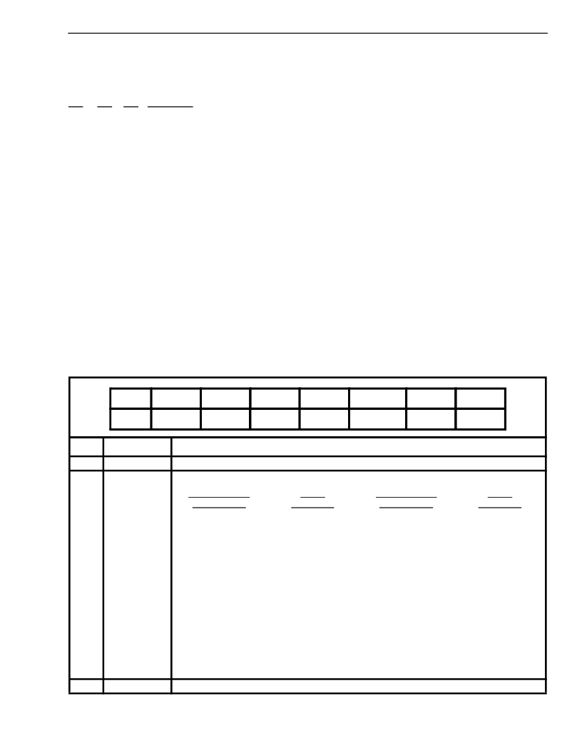
Table 6. Status Register 2
Note 1) Not Production Tested
Bit
Name
Description
7,6
SRID1, SRID0
Status Register ID. Always reads 0, 1, respectively, when Status Register 2 is output.
5,4,3,
2,1
QSNR4,
QSNR3,
QSNR2,
QSNR1,
QSNR0
Quantizer Signal to Noise Ratio Bits. (see Note 1)
QSNR4 (MSB) -
QSNR0 (LSB)
00000
00001
00010
00011
00100
00101
00110
00111
01000
01001
01010
01011
01100
01101
01110
01111
MEAN
QSNR (dB)
>36.1
36.1
30.1
26.6
24.1
22.2
20.6
19.2
18.1
17.1
16.1
15.3
14.6
13.9
13.2
12.6
QSNR4 (MSB) -
QSNR0 (LSB)
10000
10001
10010
10011
10100
10101
10110
10111
11000
11001
11010
11011
11100
11101
11110
11111
MEAN
QSNR( dB)
12.1
11.5
11.0
10.6
10.1
9.7
9.3
8.9
8.5
8.2
7.9
7.5
7.2
6.9
6.6
6.3
0
NA
Reserved. Always reads 0.
bit 7
bit 6
bit 5
bit 4
bit 3
bit 2
bit 1
bit 0
SRID1
SRID0
QSNR4
QSNR3
QSNR2
QSNR1
QSNR0
NA
相關(guān)PDF資料 |
PDF描述 |
|---|---|
| MT8910-1AP | CMOS ST-BUS⑩ FAMILY Digital Subscriber Line Interface Circuit |
| MT8920 | ISO-CMOS ST-BUS⑩ FAMILY ST-BUS Parallel Access Circuit |
| MT8920B | ISO-CMOS ST-BUS⑩ FAMILY ST-BUS Parallel Access Circuit |
| MT8920B-1 | ISO-CMOS ST-BUS⑩ FAMILY ST-BUS Parallel Access Circuit |
| MT8920BC | ISO-CMOS ST-BUS⑩ FAMILY ST-BUS Parallel Access Circuit |
相關(guān)代理商/技術(shù)參數(shù) |
參數(shù)描述 |
|---|---|
| MT8910-1AP | 制造商:MITEL 制造商全稱:Mitel Networks Corporation 功能描述:CMOS ST-BUS⑩ FAMILY Digital Subscriber Line Interface Circuit |
| MT8920 | 制造商:MITEL 制造商全稱:Mitel Networks Corporation 功能描述:ISO-CMOS ST-BUS⑩ FAMILY ST-BUS Parallel Access Circuit |
| MT8920AE | 制造商:Mitel Networks Corporation 功能描述: |
| MT8920B | 制造商:MITEL 制造商全稱:Mitel Networks Corporation 功能描述:ISO-CMOS ST-BUS⑩ FAMILY ST-BUS Parallel Access Circuit |
| MT8920B-1 | 制造商:MITEL 制造商全稱:Mitel Networks Corporation 功能描述:ISO-CMOS ST-BUS⑩ FAMILY ST-BUS Parallel Access Circuit |
發(fā)布緊急采購,3分鐘左右您將得到回復。