- 您現(xiàn)在的位置:買賣IC網(wǎng) > PDF目錄30997 > MR2510G (ON SEMICONDUCTOR) 25 A, 1000 V, SILICON, RECTIFIER DIODE PDF資料下載
參數(shù)資料
| 型號(hào): | MR2510G |
| 廠商: | ON SEMICONDUCTOR |
| 元件分類: | 整流器 |
| 英文描述: | 25 A, 1000 V, SILICON, RECTIFIER DIODE |
| 封裝: | PLASTIC, 2 PIN |
| 文件頁數(shù): | 4/7頁 |
| 文件大?。?/td> | 125K |
| 代理商: | MR2510G |
MR2502, MR2504, MR2510
http://onsemi.com
374
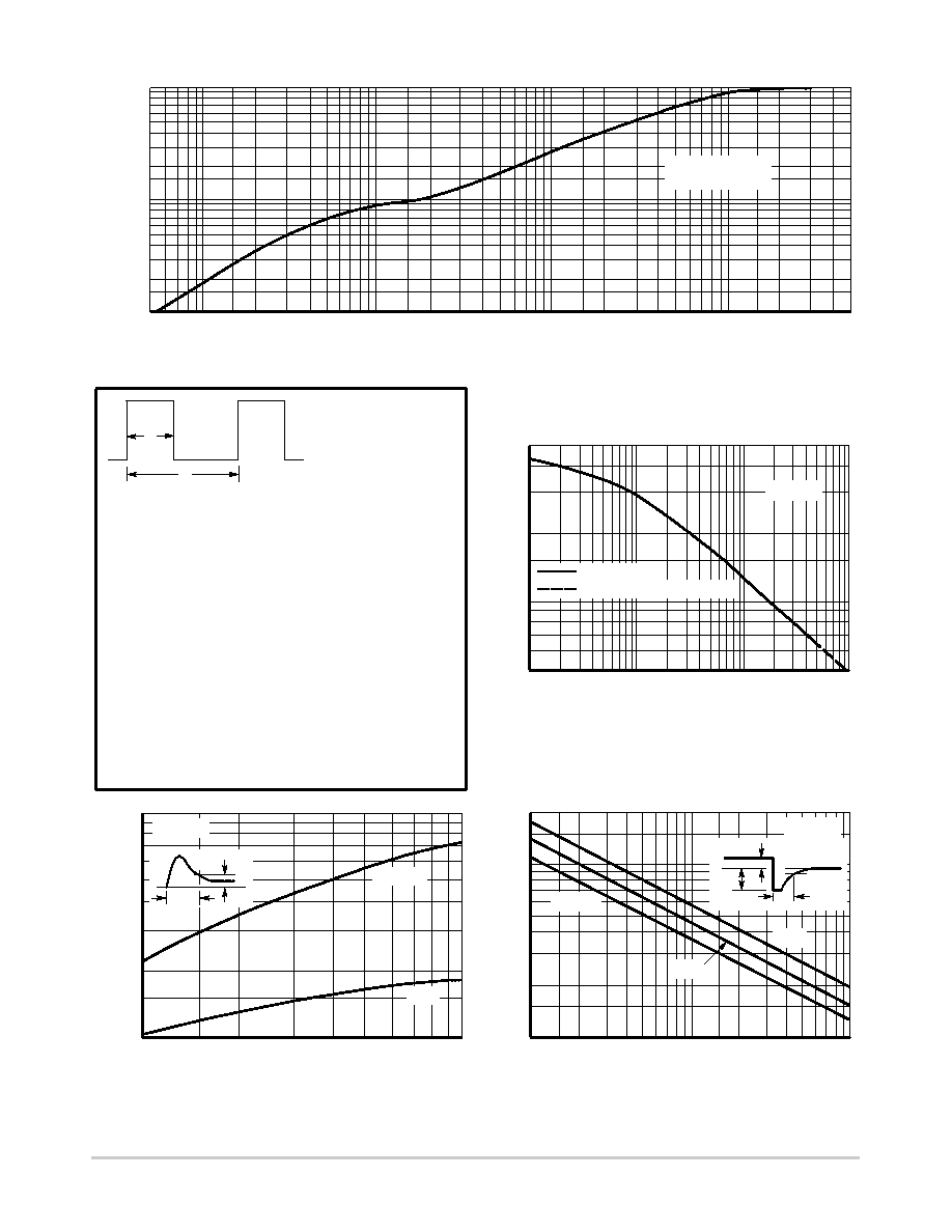
To determine maximum junction temperature of the diode in a
given situation, the following procedure is recommended:
DUTY CYCLE, D = tp/t1
PEAK POWER, Ppk, is peak of an
equivalent square power pulse.
The temperature of the case should be measured using a
thermocouple placed on the case at the temperature reference
point (see the outline drawing on page 1). The thermal mass
connected to the case is normally large enough so that it will not
significantly respond to heat surges generated in the diode as a
result of pulsed operation once steadystate conditions are
achieved. Using the measured value of TC, the junction
temperature may be determined by:
TJ = TC + n TJC
where
n TJC is the increase in junction temperature above the case
temperature, it may be determined by:
n TJC = Ppk@RθJC [D + (1 * D)@r(t1 + tp) + r(tp) *r(t1)] where
r(t) = normalized value of transient thermal resistance at time, t,
from Figure 6, i.e.:
r (t1 + tp) = normalized value of transient thermal resistance at
time t1 + tp.
t1
tp
Ppk
TIME
Figure 6. Thermal Response
Figure 7. Capacitance
Figure 8. Forward Recovery Time
Figure 9. Reverse Recovery Time
t, TIME (ms)
100
1.0
0.5
0.07
0.05
0.01
VR, REVERSE VOLTAGE (VOLTS)
1.0
0.1
500
300
200
100
70
50
2.0
1.0
IF, FORWARD CURRENT (AMP)
0.7
0.5
0.3
0.2
0.1
IR/IF, RATIO OF REVERSE TO FORWARD CURRENT
0.2
0.1
20
7.0
5.0
2.0
1.0
7.0
2.0
C,
CAP
ACIT
ANCE
(pF)
2.0
5.0
10
20
50
0.3
0.7
1.0
10
20
100
,FOR
W
ARD
RECOVER
Y
TIME
(
s)
t fr
5.0
3.0
1.0
0.3
0.5
10
3.0
t rr
,REVERSE
RECOVER
Y
TIME
(
s)
0.2
5.0
50
7.0
10
r(t),
TRANSIENT
THERMAL
RESIST
ANCE
0.2
0.1
0.03
0.02
0.05 0.07 0.1
0.2
0.3
0.5 0.7
3.0
30
200
300
500
0.5
m
10
0.7 1.0
2.0
3.0
5.0
7.0
70
RqJC(t) = RqJC r(t)
NOTE 1
TJ = 25°C
ALL DEVICES
ALL DEVICES EXCEPT MR2500
2.0 V
ufr = 1.0 V
TJ = 25°C
IF = 10 A
5.0 A
1.0 A
ufr
uf
tfr
IF
0
IR
0.25 IR
trr
(NORMALIZED)
相關(guān)PDF資料 |
PDF描述 |
|---|---|
| MR3025G | 25 A, 250 V, SILICON, RECTIFIER DIODE |
| MR850-G | 3 A, 50 V, SILICON, RECTIFIER DIODE, DO-201AD |
| MR851-G | 3 A, 100 V, SILICON, RECTIFIER DIODE, DO-201AD |
| MR852-G | 3 A, 200 V, SILICON, RECTIFIER DIODE, DO-201AD |
| MR856-G | 3 A, 600 V, SILICON, RECTIFIER DIODE, DO-201AD |
相關(guān)代理商/技術(shù)參數(shù) |
參數(shù)描述 |
|---|---|
| MR2510L | 制造商:EIC 制造商全稱:EIC discrete Semiconductors 功能描述:AUTOMOTIVE RECTIFIER DIODES |
| MR2512 | 制造商:EIC 制造商全稱:EIC discrete Semiconductors 功能描述:AUTOMOTIVE RECTIFIER DIODES |
| MR2512L | 制造商:EIC 制造商全稱:EIC discrete Semiconductors 功能描述:AUTOMOTIVE RECTIFIER DIODES |
發(fā)布緊急采購,3分鐘左右您將得到回復(fù)。