- 您現(xiàn)在的位置:買賣IC網(wǎng) > PDF目錄45342 > MPC5607BVLL4R (FREESCALE SEMICONDUCTOR INC) FLASH, 48 MHz, MICROCONTROLLER, PQFP100 PDF資料下載
參數(shù)資料
| 型號: | MPC5607BVLL4R |
| 廠商: | FREESCALE SEMICONDUCTOR INC |
| 元件分類: | 微控制器/微處理器 |
| 英文描述: | FLASH, 48 MHz, MICROCONTROLLER, PQFP100 |
| 封裝: | 14 X 14 MM, 1.40 MM HEIGHT, MS-026 BED, LQFP-100 |
| 文件頁數(shù): | 62/106頁 |
| 文件大?。?/td> | 667K |
| 代理商: | MPC5607BVLL4R |
第1頁第2頁第3頁第4頁第5頁第6頁第7頁第8頁第9頁第10頁第11頁第12頁第13頁第14頁第15頁第16頁第17頁第18頁第19頁第20頁第21頁第22頁第23頁第24頁第25頁第26頁第27頁第28頁第29頁第30頁第31頁第32頁第33頁第34頁第35頁第36頁第37頁第38頁第39頁第40頁第41頁第42頁第43頁第44頁第45頁第46頁第47頁第48頁第49頁第50頁第51頁第52頁第53頁第54頁第55頁第56頁第57頁第58頁第59頁第60頁第61頁當(dāng)前第62頁第63頁第64頁第65頁第66頁第67頁第68頁第69頁第70頁第71頁第72頁第73頁第74頁第75頁第76頁第77頁第78頁第79頁第80頁第81頁第82頁第83頁第84頁第85頁第86頁第87頁第88頁第89頁第90頁第91頁第92頁第93頁第94頁第95頁第96頁第97頁第98頁第99頁第100頁第101頁第102頁第103頁第104頁第105頁第106頁
Electrical characteristics
MPC5607B Microcontroller Data Sheet, Rev. 5
Freescale Semiconductor
59
4.10.3
Start-up/Switch-off timings
4.11
Electromagnetic compatibility (EMC) characteristics
Susceptibility tests are performed on a sample basis during product characterization.
4.11.1
Designing hardened software to avoid noise problems
EMC characterization and optimization are performed at component level with a typical application environment and simplified
MCU software. It should be noted that good EMC performance is highly dependent on the user application and the software in
particular.
Therefore it is recommended that the user apply EMC software optimization and prequalification tests in relation with the EMC
level requested for the application.
Software recommendations
The software flowchart must include the management of runaway conditions such as:
— Corrupted program counter
— Unexpected reset
— Critical data corruption (control registers...)
Prequalification trials
Most of the common failures (unexpected reset and program counter corruption) can be
reproduced by manually forcing a low state on the reset pin or the oscillator pins for 1 second.
To complete these trials, ESD stress can be applied directly on the device. When unexpected behavior is detected, the
software can be hardened to prevent unrecoverable errors occurring.
4.11.2
Electromagnetic interference (EMI)
The product is monitored in terms of emission based on a typical application. This emission test conforms to the IEC61967-1
standard, which specifies the general conditions for EMI measurements.
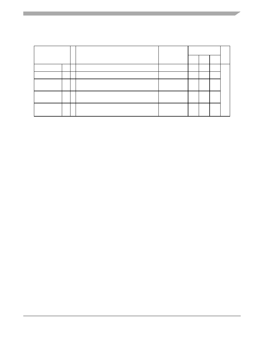
Table 29. Start-up time/Switch-off time
Symbol
C
Parameter
Conditions1
1 V
DD = 3.3 V ± 10% / 5.0 V ± 10%, TA = 40 to 125 °C, unless otherwise specified
Value
Unit
Min
Typ
Max
TFLARSTEXIT
CC T Delay for Flash module to exit reset mode
—
125
s
TFLALPEXIT
CC T Delay for Flash module to exit low-power mode
—
0.5
TFLAPDEXIT
CC T Delay for Flash module to exit power-down
mode
——
—
30
TFLALPENTRY
CC T Delay for Flash module to enter low-power
mode
——
—
0.5
TFLAPDENTRY
CC T Delay for Flash module to enter power-down
mode
——
—
1.5
相關(guān)PDF資料 |
PDF描述 |
|---|---|
| MPC5607BCMG4 | FLASH, 48 MHz, MICROCONTROLLER, PBGA208 |
| MPC5607BCLL6R | FLASH, 64 MHz, MICROCONTROLLER, PQFP100 |
| MPC5607BMLU6R | FLASH, 64 MHz, MICROCONTROLLER, PQFP176 |
| MPC5607BMMG6R | FLASH, 64 MHz, MICROCONTROLLER, PBGA208 |
| MPC5607BMLU4 | FLASH, 48 MHz, MICROCONTROLLER, PQFP176 |
相關(guān)代理商/技術(shù)參數(shù) |
參數(shù)描述 |
|---|---|
| MPC5607CECLLR | 制造商:FREESCALE 制造商全稱:Freescale Semiconductor, Inc 功能描述:Microcontroller |
| MPC5607CECLQR | 制造商:FREESCALE 制造商全稱:Freescale Semiconductor, Inc 功能描述:Microcontroller |
| MPC5607CECLUR | 制造商:FREESCALE 制造商全稱:Freescale Semiconductor, Inc 功能描述:Microcontroller |
| MPC5607CEMLLR | 制造商:FREESCALE 制造商全稱:Freescale Semiconductor, Inc 功能描述:Microcontroller |
| MPC5607CEMLQR | 制造商:FREESCALE 制造商全稱:Freescale Semiconductor, Inc 功能描述:Microcontroller |
發(fā)布緊急采購,3分鐘左右您將得到回復(fù)。