- 您現(xiàn)在的位置:買賣IC網(wǎng) > PDF目錄98023 > MM908E621ACDWB (FREESCALE SEMICONDUCTOR INC) 8-BIT, FLASH, 8 MHz, MICROCONTROLLER, PDSO54 PDF資料下載
參數(shù)資料
| 型號(hào): | MM908E621ACDWB |
| 廠商: | FREESCALE SEMICONDUCTOR INC |
| 元件分類: | 微控制器/微處理器 |
| 英文描述: | 8-BIT, FLASH, 8 MHz, MICROCONTROLLER, PDSO54 |
| 封裝: | 17.90 X 7.50 MM, 0.65 MM PITCH, PLASTIC, SOIC-54 |
| 文件頁數(shù): | 32/62頁 |
| 文件大小: | 917K |
| 代理商: | MM908E621ACDWB |
第1頁第2頁第3頁第4頁第5頁第6頁第7頁第8頁第9頁第10頁第11頁第12頁第13頁第14頁第15頁第16頁第17頁第18頁第19頁第20頁第21頁第22頁第23頁第24頁第25頁第26頁第27頁第28頁第29頁第30頁第31頁當(dāng)前第32頁第33頁第34頁第35頁第36頁第37頁第38頁第39頁第40頁第41頁第42頁第43頁第44頁第45頁第46頁第47頁第48頁第49頁第50頁第51頁第52頁第53頁第54頁第55頁第56頁第57頁第58頁第59頁第60頁第61頁第62頁
Analog Integrated Circuit Device Data
38
Freescale Semiconductor
908E621
FUNCTIONAL DEVICE OPERATION
OPERATIONAL MODES
Half-Bridge Control
Each output MOSFET can be controlled individually. The
general enable of the circuitry is done by setting PSON in the
System Control Register (SYSCTL). The HBx_L and HBx_H
bits form one half bridge. It is not possible to switch on both
MOSFETs in one half-bridge at the same time. If both bits are
set, the high-side MOSFET is in PWM mode.
To avoid both MOSFETs (high-side and low-side) of one
half-bridge being on at the same time, a break-before-make
circuit exists. Switching the high-side MOSFET on is inhibited
as long as the potential between gate and VSS is not below a
certain threshold. Switching the low-side MOSFET on is
blocked as long as the potential between gate and source of
the high-side MOSFET did not fall below a certain threshold.
HALF-BRIDGE OUTPUT REGISTER (HBOUT)
HBx_H, HBx_L — Half Bridge Output Switches
These read/write bits select the output of each half-bridge
output according to the following table.
Reset clears all HBx_H, HBx_L bits.
Table 9. Half-Bridge Configuration
Half-Bridge PWM mode
The PWM mode is selected by setting both HBxL and
HBxH of one Half-bridge to “1”. In this mode the high-side
MOSFET is controlled by the incoming PWM signal on the
PWM terminal (see Figure 2, page 2).
If the incoming signal is high, the high-side MOSFET is
switched on.
If the incoming signal is low, the high-side MOSFET is
switched off.
With the current recirculation mode control bit CRM in the
Half-Bridge Status and Control Register (HBSCTL) the
recirculation behavior in PWM mode can be controlled. If
CRM is set the corresponding low-side MOSFET is switched
on if the PWM controlled high-side MOSFET is off.
Half-Bridge Current Recopy
Each low-side MOSFET has an additional sense output to
allow a current recopy feature. These sense sources are
internally amplified and switched to the Analog Multiplexer.
The factor for the Current Sense amplification can be
selected via bit CSA in the A0MUCTL register (see page 32)
CSA = “1”: low resolution selected
CSA = “0”: high resolution selected
Half-Bridge Overtemperature Protection
The outputs are protected against overtemperature
conditions. Each power output comprises two different
temperature thresholds.
The first threshold is the high temperature interrupt (HTI).
If the temperature reaches this threshold the HTIF bit in the
Interrupt Flag Register (IFR) is set and an interrupt will be
initiated if HTIE bit in the Interrupt Mask register is set. In
addition this interrupt can be used to automatically turn off the
power stages. This shutdown can be enabled/disabled by
Bits HTIS0-1 in the System Control Register (SYSCTL).
The high temperature interrupts flag (HTIF) is cleared (and
the outputs reenabled) by writing a “1” to the HTIF flag in the
Interrupt Flag Register (IFR) or by a reset. Clearing this flag
has no effect as long as a high temperature condition is
present.
If the HTI shutdown is disabled, a second threshold high
temperature reset (HTR) will be used to turn off all power
stages (HB (all Fet’s), HS, HVDD, H0) in order to protect the
device.
Half-Bridge Overcurrent Protection
The Half-Bridges are protected against short to GND,
VSUP and load shorts. The overcurrent protection is
implemented on each HB. If a overcurrent condition on the
high-side MOSFET occurs the high-side MOSFET is
automatically switched off. An overcurrent condition on the
low-side MOSFET will automatically turn off the low-side
MOSFET. In both cases the corresponding HBxOCF flag in
the Half-Bridge Status and Control Register (HBSCTL) is set.
The overcurrent status flag is cleared (and the
corresponding Half-Bridge MOSFETs reenabled) by writing a
“1” to the HBxOCF in the Half-Bridge Status and Control
Register (HBSCTL) or by a reset.
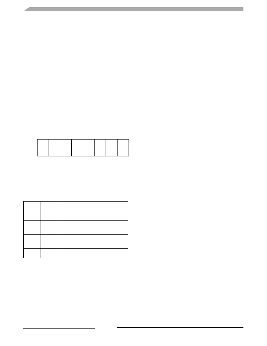
Register Name and Address: HBOUT - $01
Bit7
6
5
4
3
2
1
Bit0
Read
HB4_H
HB4_L
HB3_H
HB3_L
HB2_H
HB2_L
HB1_H
HB1_L
Write
Reset
0
HBx_H
HBx_L
Mode
00
Low-side and high-side MOSFET off
01
High-side MOSFET off,
low-side MOSFET on
10
High-side MOSFET on,
low-side MOSFET off
11
High-side MOSFET in PWM mode
相關(guān)PDF資料 |
PDF描述 |
|---|---|
| MM908E622ACDWB/R2 | 8-BIT, FLASH, 8 MHz, MICROCONTROLLER, PDSO54 |
| MM908E624ACDWB/R | 8-BIT, FLASH, 8 MHz, MICROCONTROLLER, PDSO54 |
| MM908E625ACDWB | 8-BIT, FLASH, 8 MHz, MICROCONTROLLER, PDSO54 |
| MMBD1010LT3 | 0.2 A, 2 ELEMENT, SILICON, SIGNAL DIODE, TO-236AB |
| MMBD3000T1 | 0.2 A, SILICON, SIGNAL DIODE |
相關(guān)代理商/技術(shù)參數(shù) |
參數(shù)描述 |
|---|---|
| MM908E621ACDWB/R2 | 制造商:FREESCALE 制造商全稱:Freescale Semiconductor, Inc 功能描述:Integrated Quad Half-bridge and Triple High Side with Embedded MCU and LIN for High End Mirror |
| MM908E621ACDWBR2 | 功能描述:8位微控制器 -MCU QUAD HB / TRIPLE HS 841B RoHS:否 制造商:Silicon Labs 核心:8051 處理器系列:C8051F39x 數(shù)據(jù)總線寬度:8 bit 最大時(shí)鐘頻率:50 MHz 程序存儲(chǔ)器大小:16 KB 數(shù)據(jù) RAM 大小:1 KB 片上 ADC:Yes 工作電源電壓:1.8 V to 3.6 V 工作溫度范圍:- 40 C to + 105 C 封裝 / 箱體:QFN-20 安裝風(fēng)格:SMD/SMT |
| MM908E621ACPEK | 功能描述:8位微控制器 -MCU QUAD H-B/3-HS W/MCU & LI RoHS:否 制造商:Silicon Labs 核心:8051 處理器系列:C8051F39x 數(shù)據(jù)總線寬度:8 bit 最大時(shí)鐘頻率:50 MHz 程序存儲(chǔ)器大小:16 KB 數(shù)據(jù) RAM 大小:1 KB 片上 ADC:Yes 工作電源電壓:1.8 V to 3.6 V 工作溫度范圍:- 40 C to + 105 C 封裝 / 箱體:QFN-20 安裝風(fēng)格:SMD/SMT |
| MM908E621ACPEKR2 | 功能描述:8位微控制器 -MCU QUAD HB AND TRIPLE HS RoHS:否 制造商:Silicon Labs 核心:8051 處理器系列:C8051F39x 數(shù)據(jù)總線寬度:8 bit 最大時(shí)鐘頻率:50 MHz 程序存儲(chǔ)器大小:16 KB 數(shù)據(jù) RAM 大小:1 KB 片上 ADC:Yes 工作電源電壓:1.8 V to 3.6 V 工作溫度范圍:- 40 C to + 105 C 封裝 / 箱體:QFN-20 安裝風(fēng)格:SMD/SMT |
| MM908E622 | 制造商:FREESCALE 制造商全稱:Freescale Semiconductor, Inc 功能描述:Integrated Quad Half-Bridge, Triple High-Side and EC Glass Driver with Embedded MCU and LIN for High End Mirror |
發(fā)布緊急采購,3分鐘左右您將得到回復(fù)。