- 您現(xiàn)在的位置:買賣IC網(wǎng) > PDF目錄383602 > MH89760BS (Mitel Networks Corporation) Ultraframer DS3/E3/DS2/E2/DS1/E1/DS0 PDF資料下載
參數(shù)資料
| 型號: | MH89760BS |
| 廠商: | Mitel Networks Corporation |
| 元件分類: | 通信及網(wǎng)絡(luò) |
| 英文描述: | Ultraframer DS3/E3/DS2/E2/DS1/E1/DS0 |
| 中文描述: | Ultraframer DS3/E3/DS2/E2/DS1/E1/DS0 |
| 文件頁數(shù): | 23/38頁 |
| 文件大小: | 846K |
| 代理商: | MH89760BS |
第1頁第2頁第3頁第4頁第5頁第6頁第7頁第8頁第9頁第10頁第11頁第12頁第13頁第14頁第15頁第16頁第17頁第18頁第19頁第20頁第21頁第22頁當(dāng)前第23頁第24頁第25頁第26頁第27頁第28頁第29頁第30頁第31頁第32頁第33頁第34頁第35頁第36頁第37頁第38頁
4-77
Preliminary Information
MH89760B
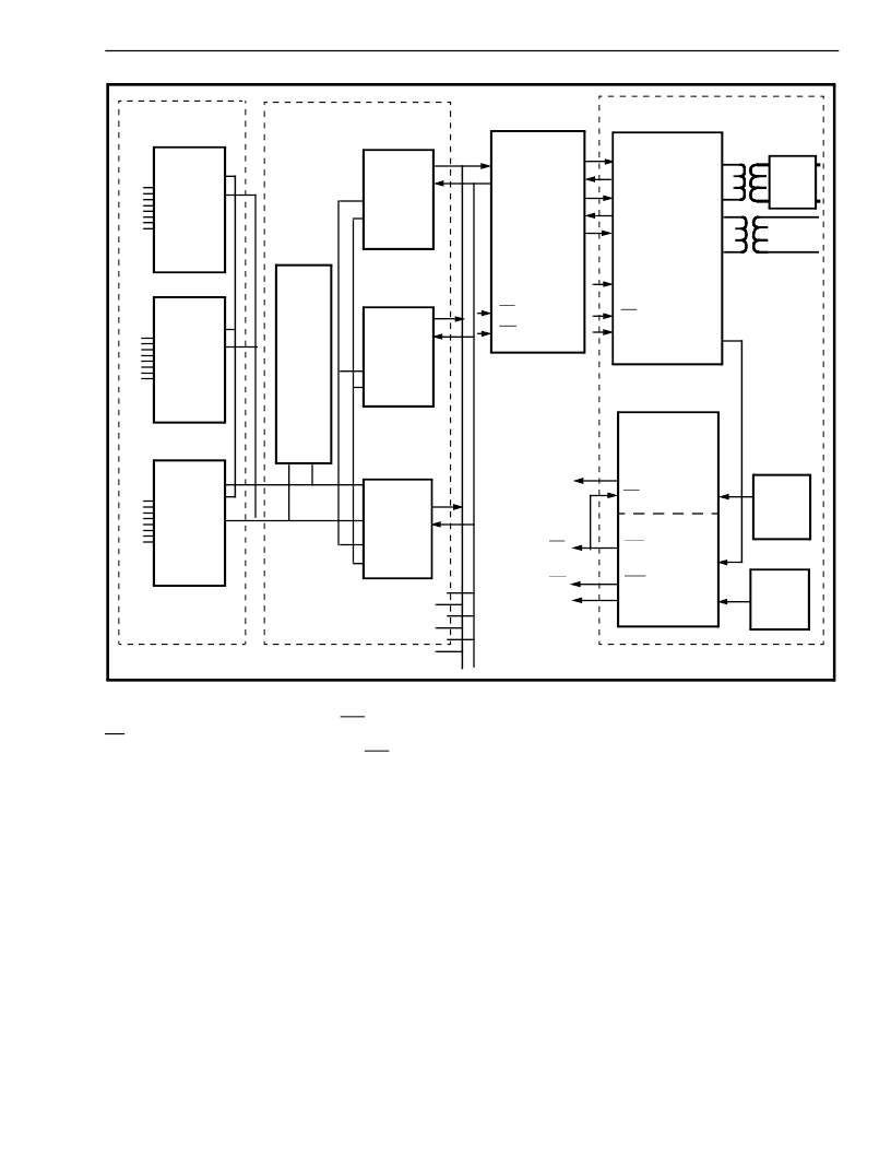
Figure 16 - Digital Multiplex Interface (DMI)
Asynchronous
Interface
Protocol Converter
Switch Matrix
T1 Interface
R
S
2
3
2
ACIA
A
0
-A
7
D
0
-D
7
A
0
-A
7
A
0
-A
7
D
0
-D
7
D
0
-D
7
ACIA
ACIA
Micro
68008
MT8952
MT8952
MT8952
D
0
-D
7
A
0
-A
7
D
0
-D
7
A
0
-A
7
D
0
-D
7
A
0
-A
7
MT8941
DPLL #1
STo3
STi2
STo2
STi1
STo1
C4i
F0i
STo0
STi0
F0i
F0i
C1.5i
C4i
C2i
C2i
C1.5i
OUTA
OUTB
RxT
RxR
E8Ko
CSTi1
CSTo
CSTi0
DSTo
DSTi
izer
Equal-
CVb
F0i
C12i
C4b
C20
F0b
C8Kb
DPLL #2
12.352
MHz
Osc.
MHz
Osc.
16.384
R
S
2
3
2
R
S
2
3
2
MT8980
MT89760B
connecting the frame pulse output, F0o, of PLL #2 to
F0i of PLL # 1, the MT8941 will generate the T1
transmit clock that is phase-locked to F0o, which in
turn is phase-locked to the master synchronization
signal, E8Ko. If all of the T1 trunks are from the
network any short term differences in the received
data rate will be absorbed by the elastic buffer in the
MH89760B.
6. Digital Multiplex Interface (DMI)
Figure 16 illustrates an implementation of the Digital
Multiplex Interface (DMI) specification, which defines
a computer to PBX interface. This interface can
convert 300 baud to 64 kbaud asynchronous or
synchronous data channels to T1 format with clear
channel capabilities and common channel signalling.
Figure 16 is broken down into four functional blocks
which are the asynchronous interface (ACIAs), the
protocol converter (micro and MT8952s), the switch
matrix (MT8980), and the T1 interface (MH89760B).
The
Adapters (ACIA) provide a standard RS232 interface
that is compatible with many off-the-shelf modems
and data sets. A single microprocessor is capable of
handling the protocol conversion between the RS232
ports and the MT8952 HDLC protocol controller.
Asynchronous
Communications
Interface
The MT8952 interfaces directly to the ST-BUS, which
in turn interfaces directly to the T1 interface devices.
Instead of the MT8952 operating at 64 kbit/s
continuously, it operates at 2.048 Mbit/s and
inputs/outputs an 8 bit burst every 125 μsec. This
feature eliminates the need for an additional rate
conversion circuit to multiplex the HDLC outputs up
to the T1 data rate. Each of the HDLC chips is
assigned a timeslot on the ST-BUS in a manner that
is similar to enabling a voice codec. When the
MT8952 is not enabled the output driver is tristated.
相關(guān)PDF資料 |
PDF描述 |
|---|---|
| MH89761 | T1 Transmit Equalizer Advance Information |
| MH89770N | Ultraframer DS3/E3/DS2/E2/DS1/E1/DS0 |
| MH89770 | Ultraframer DS3/E3/DS2/E2/DS1/E1/DS0 |
| MH89770S | Ultraframer DS3/E3/DS2/E2/DS1/E1/DS0 |
| MH89790B | Ultraframer DS3/E3/DS2/E2/DS1/E1/DS0 |
相關(guān)代理商/技術(shù)參數(shù) |
參數(shù)描述 |
|---|---|
| MH89761 | 制造商:MITEL 制造商全稱:Mitel Networks Corporation 功能描述:T1 Transmit Equalizer Advance Information |
| MH89770 | 制造商:MITEL 制造商全稱:Mitel Networks Corporation 功能描述:T1/ESF Framer & Interface Preliminary Information |
| MH89770N | 制造商:MITEL 制造商全稱:Mitel Networks Corporation 功能描述:T1/ESF Framer & Interface Preliminary Information |
| MH89770S | 制造商:MITEL 制造商全稱:Mitel Networks Corporation 功能描述:T1/ESF Framer & Interface Preliminary Information |
| MH89790B | 制造商:MITEL 功能描述: 制造商:ZARLNK 功能描述: |
發(fā)布緊急采購,3分鐘左右您將得到回復(fù)。