- 您現在的位置:買賣IC網 > PDF目錄45193 > MB91101APF-G-JNE1 (FUJITSU LTD) 32-BIT, 50 MHz, RISC MICROCONTROLLER, PQFP100 PDF資料下載
參數資料
| 型號: | MB91101APF-G-JNE1 |
| 廠商: | FUJITSU LTD |
| 元件分類: | 微控制器/微處理器 |
| 英文描述: | 32-BIT, 50 MHz, RISC MICROCONTROLLER, PQFP100 |
| 封裝: | 14 X 20 MM, 3.35 MM HEIGHT, 0.65 MM PITCH, PLASTIC, QFP-100 |
| 文件頁數: | 10/100頁 |
| 文件大?。?/td> | 2083K |
| 代理商: | MB91101APF-G-JNE1 |
第1頁第2頁第3頁第4頁第5頁第6頁第7頁第8頁第9頁當前第10頁第11頁第12頁第13頁第14頁第15頁第16頁第17頁第18頁第19頁第20頁第21頁第22頁第23頁第24頁第25頁第26頁第27頁第28頁第29頁第30頁第31頁第32頁第33頁第34頁第35頁第36頁第37頁第38頁第39頁第40頁第41頁第42頁第43頁第44頁第45頁第46頁第47頁第48頁第49頁第50頁第51頁第52頁第53頁第54頁第55頁第56頁第57頁第58頁第59頁第60頁第61頁第62頁第63頁第64頁第65頁第66頁第67頁第68頁第69頁第70頁第71頁第72頁第73頁第74頁第75頁第76頁第77頁第78頁第79頁第80頁第81頁第82頁第83頁第84頁第85頁第86頁第87頁第88頁第89頁第90頁第91頁第92頁第93頁第94頁第95頁第96頁第97頁第98頁第99頁第100頁
MB91101 Series
DS07-16301-6E
17
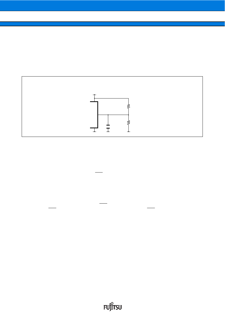
10. Internal DC Regulator
Internal DC regulator stops in stop mode. When the regulator stops owing to the increase of inner leakage
current (ICCH) in stop mode, malfunction caused by noise or any troubles about power supply in normal
operation, the internal 3 V power supply voltage may decrease less than the warranty range for normal
operation. So when using the internal regulator and stop mode with 5 V power supply, never fail to support
externally so that 3 V power supply voltage might not decrease. However, even in such a case, the internal
regulator can be restarted by inputting the reset procedure. (In this case, set the reset to “L” level within the
oscillation stabilizing waiting time.)
11. Pin Condition at Turning on the Power Supply
The pin condition at turning on the power supply is unstable. The circuit starts being initialized after turning
on the power supply and then starting oscillation and then the operation of the internal regulator becomes
stable. So it takes about 42 ms for the pin to be initialized from the oscillation starting at the source oscillation
12.5 MHz. Take care that the pin condition may be output condition at initial unstable condition.
(With the MB91101A, however, initalization can be achieved in less than about 42 ms after turning on the
internal power supply by maintaining the RST pin at "L" level.)
12. Source Oscillation Input at Turning on the Power Supply
At turning on the power supply, never fail to input the clock before cancellation of the oscillation stabilizing
waiting.
13. Hardware Stand-by at Turning on the Power Supply
When turning on the power supply with the HST pin being set to “L” level, the hardware does not stand by.
However the HST pin becomes available after the reset cancellation, the HST pin must once be back to “H”
level.
14. Power on Reset
Make sure to make power on reset at turning on the power supply or returning on the power supply when
the power supply voltage is below the warranty range for normal operation.
15. Notes on during operation of PLL clock mode
If the PLL clock mode is selected, the microcontroller attempt to be working with the self oscillating circuit
evevn when there is no external oscillator or external clock input is stopped. Performance of this operation,
however, cannot be guaranteed.
16. Watchdog timer function
The watchdog timer supported by the FR family monitors the program that performs the reset delay operation
for a specified time. If the program hangs up and the reset delay operation is not performed, the watchdog
timer resets the CPU. Therefore, once the watchdog timer is enabled, operation continues until the CPU is
reset.
As an exception, a reset delay automatically occurs if the CPU stops program execution.
VCC5
VCC3
VSS
3.6 k
Ω
6.8 k
Ω
0.1
μF
approx.
5 V
Using STOP mode with 5 V power supply
相關PDF資料 |
PDF描述 |
|---|---|
| MB91106PFV-XXX | 32-BIT, MROM, 50 MHz, RISC MICROCONTROLLER, PQFP100 |
| MB91107APMC1 | RISC MICROCONTROLLER, PQFP120 |
| MB91107APFV | RISC MICROCONTROLLER, PQFP120 |
| MB911110PMT2 | 32-BIT, 50 MHz, RISC MICROCONTROLLER, PQFP144 |
| MB91133PMC-XXX | 32-BIT, MROM, 33 MHz, RISC MICROCONTROLLER, PQFP144 |
相關代理商/技術參數 |
參數描述 |
|---|---|
| MB91101APFR-G-JNE1 | 制造商:FUJITSU 功能描述: |
| MB91101APFV | 制造商:FUJITSU 制造商全稱:Fujitsu Component Limited. 功能描述:32-bit RISC Microcontroller |
| MB91106 | 制造商:FUJITSU 制造商全稱:Fujitsu Component Limited. 功能描述:32-bit RISC Microcontroller |
| MB91106PF | 制造商:FUJITSU 制造商全稱:Fujitsu Component Limited. 功能描述:32-bit RISC Microcontroller |
| MB91106PFV | 制造商:FUJITSU 制造商全稱:Fujitsu Component Limited. 功能描述:32-bit RISC Microcontroller |
發(fā)布緊急采購,3分鐘左右您將得到回復。