- 您現在的位置:買賣IC網 > PDF目錄45186 > MB89PV950CF 8-BIT, 5 MHz, MICROCONTROLLER, CQFP64 PDF資料下載
參數資料
| 型號: | MB89PV950CF |
| 元件分類: | 微控制器/微處理器 |
| 英文描述: | 8-BIT, 5 MHz, MICROCONTROLLER, CQFP64 |
| 封裝: | 0.80 MM PITCH, PIGGY BACK, MQFP-64 |
| 文件頁數: | 106/110頁 |
| 文件大?。?/td> | 619K |
| 代理商: | MB89PV950CF |
第1頁第2頁第3頁第4頁第5頁第6頁第7頁第8頁第9頁第10頁第11頁第12頁第13頁第14頁第15頁第16頁第17頁第18頁第19頁第20頁第21頁第22頁第23頁第24頁第25頁第26頁第27頁第28頁第29頁第30頁第31頁第32頁第33頁第34頁第35頁第36頁第37頁第38頁第39頁第40頁第41頁第42頁第43頁第44頁第45頁第46頁第47頁第48頁第49頁第50頁第51頁第52頁第53頁第54頁第55頁第56頁第57頁第58頁第59頁第60頁第61頁第62頁第63頁第64頁第65頁第66頁第67頁第68頁第69頁第70頁第71頁第72頁第73頁第74頁第75頁第76頁第77頁第78頁第79頁第80頁第81頁第82頁第83頁第84頁第85頁第86頁第87頁第88頁第89頁第90頁第91頁第92頁第93頁第94頁第95頁第96頁第97頁第98頁第99頁第100頁第101頁第102頁第103頁第104頁第105頁當前第106頁第107頁第108頁第109頁第110頁
OPERATION
3– 9
3.5
Pin States For Sleep, Stop, and Reset
The state of each pin of the MB89950 series of microcontrollers at sleep, stop and reset is as follows:
(1) Sleep
The pin state immediately before the sleep state is held.
(2) Stop
The pin state immediately before the stop state is held when the stop
mode is started and bit 5 of the standby-control register (STBC) is set to
0; the impedance of the output and input/output pins goes High when the
bit is set to 1.
(3) Reset
The impedance of all I/O and peripheral pins (excluding pins for pull-up
option) goes High.
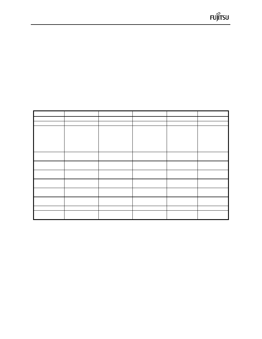
Table 3–3 Pin State of MB89950
Pin name
Normal
Sleep
Stop SPL=0
Stop SPL=1
Reset
COM0 to COM3
COM outputs
Low level outputs
Low level output
SEG00 to SEG19
Segment outputs
Low level outputs
Low level output
P00/SEG20 to
P07/SEG27
P10/SEG28 to
P17/SEG35
P20/SEG36 to
P25/SEG41
Port I/O
/Peripheral output
Port I/O
/Peripheral output
Port I/O
/Peripheral
output = Low
High impedance*1
/Peripheral
output = Low
High impedance*1
X0
Input for oscillation
High impedance*1
High impedance*1 Input for oscillation
X1
Output for oscillation Output for oscillation
High output
Output for
oscillation
MODA
Mode input
RST
Reset input
Reset input*2
P30,P31
Port I/O
High impedance*1
High impedance
P32/V1, P33/V2
Port/LCD bias
High impedance*4
/LCD bias
High impedance*5
V3
Input
P40 to P46/INT0
Port/Peripheral I/O
High
impedance*1,*3
High impedance*1
*1 The internal input level is fixed to prevent leakage due to open input . Pins for which the pull-up
option is selected, enter the pull-up state.
*2 The reset pin may serve as the output depending on the option setting.
*3 For P42 and P46, when edge detection for the external interrupt is selected, only the external
interrupt can be input even in the stop mode (SPL = 1).
*4 Whether the pins behave as I/O port or LCD bias depends on the PSEL bit of LCDR (see page 2-60).
*5 These pins are selected as LCD bias after reset. To turn P32 and P33 to ports after reset, set
PSEL bit of LCDR to 1 afterwards.
相關PDF資料 |
PDF描述 |
|---|---|
| MB89951PFM | 8-BIT, MROM, 5 MHz, MICROCONTROLLER, PQFP64 |
| MB89T623PFM | 8-BIT, 10 MHz, MICROCONTROLLER, PQFP64 |
| MB89623RP-SH | 8-BIT, MROM, 10 MHz, MICROCONTROLLER, PDIP64 |
| MB89625RPFV | 8-BIT, MROM, 10 MHz, MICROCONTROLLER, PQFP64 |
| MB89W627C-SH | 8-BIT, UVPROM, 10 MHz, MICROCONTROLLER, CDIP64 |
相關代理商/技術參數 |
參數描述 |
|---|---|
| MB89PV960 | 制造商:FUJITSU 制造商全稱:Fujitsu Component Limited. 功能描述:8-bit Proprietary Microcontroller |
| MB89PV980-101 | 制造商:FUJITSU 制造商全稱:Fujitsu Component Limited. 功能描述:8-bit Proprietary Microcontroller |
| MB89PV980-201 | 制造商:FUJITSU 制造商全稱:Fujitsu Component Limited. 功能描述:8-bit Proprietary Microcontroller |
| MB89PW625 | 制造商:FUJITSU 制造商全稱:Fujitsu Component Limited. 功能描述:8-bit Proprietary Microcontroller |
| MB89R112B1QN-G-AMERE1 | 制造商:FUJITSU 功能描述: |
發(fā)布緊急采購,3分鐘左右您將得到回復。