- 您現(xiàn)在的位置:買賣IC網(wǎng) > PDF目錄383369 > MAX3510 (Maxim Integrated Products, Inc.) 2X2 1.5 Gbps LVDS Crosspoint Switch 16-SOIC -40 to 85 PDF資料下載
參數(shù)資料
| 型號: | MAX3510 |
| 廠商: | Maxim Integrated Products, Inc. |
| 英文描述: | 2X2 1.5 Gbps LVDS Crosspoint Switch 16-SOIC -40 to 85 |
| 中文描述: | CATV上行放大器 |
| 文件頁數(shù): | 8/12頁 |
| 文件大?。?/td> | 138K |
| 代理商: | MAX3510 |

M
Ramp Generator
The ramp generator circuit is a simple RC charging cir-
cuit, which is used to control power-up and power-down
of the output power amplifier. It is made up of CEXT1
and an internal 2k
resistor. The choice of CEXT1 is gov-
erned by the period of the burst on/off cycle. CEXT1
must be small enough to fully charge/discharge within a
burst. A typical value of CEXT1 is 0.0033μF.
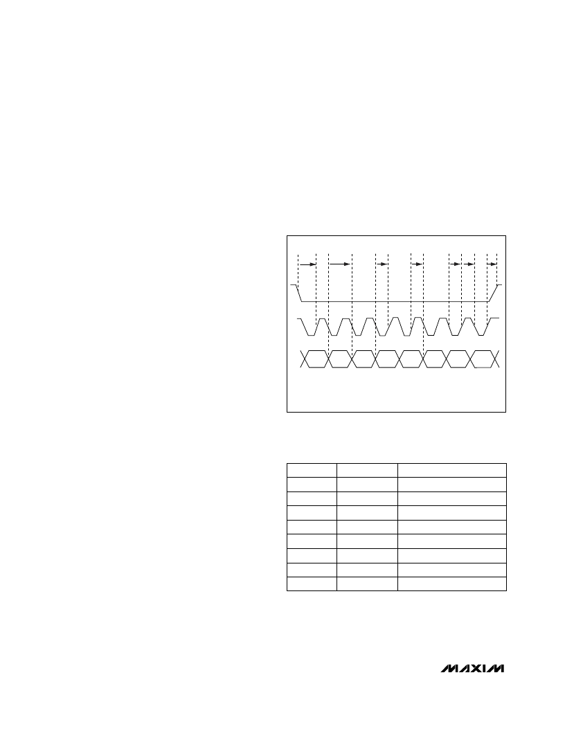
Serial Interface
The serial interface has an active-low enable (
CS
) to
bracket the data, with data clocked in MSB first on the
rising edge of SCLK. Data is stored in the storage latch
on the rising edge of
CS
. The serial interface controls the
state of the PGA. Tables 2 and 3 show the register for-
mat. Serial-interface timing is shown in Figure 2.
PGA Bias Cell
The PGA bias cell is accessed by the
SHDN
pin. When
this pin is taken low, the programmable-gain amplifier
and serial data interface are shut off. Note that any gain
setting stored in the serial data interface latch will be
lost. The power amplifier is unaffected by the PGA Bias
cell, therefore TXEN must be held low to be in shut-
down mode. This mode lowers supply current draw to
less than 1μA typical.
Power Amp Bias Cell
The power amp bias cell is used to enable and disable
bias to the output differential pair. This is controlled by
the TXEN pin (18).
Functional Modes
The MAX3510 has four functional modes controlled
through the serial interface or external pins (Table 3):
transmit mode, transmit-disable mode, software-shut-
down mode, and shutdown mode.
Transmit Mode
Transmit mode is the normal active mode of the
MAX3510. The TXEN pin must be held high in this
mode. Note that
SHDN
must also be held high.
Transmit-Disable Mode
When in transmit-disable mode, the power amplifier is
completely shut off. This mode is activated by taking
TXEN low while keeping
SHDN
high. This mode is typi-
cally used between bursts in TDMA systems. Transients
are controlled by the action of the transformer balance.
Software-Shutdown Mode
Software-shutdown mode is enabled when D7 = 0 and
TXEN is low. This mode minimizes current consumption
while maintaining the programmed gain state stored in
the latch of the serial-data interface. All analog func-
tions are disabled in this mode and current consump-
tion is reduced to under 2mA.
Shutdown Mode
In normal operation the shutdown pin (
SHDN
) is held
high. When
SHDN
and TXEN are taken low, all circuits
within the IC are disabled. Only leakage currents flow in
this state. Data stored within the serial-data interface
latches will be lost upon entering this mode. Current
draw is reduced to 1μA (typ) in shutdown mode.
Upstream CATV Amplifier
8
_______________________________________________________________________________________
BIT
Software Shutdown
D7
MSB 7
DESCRIPTION
MNEMONIC
Test Bit
D6
6
Gain Control, Bit 4
D4
4
Gain Control, Bit 5
D5
5
Gain Control, Bit 2
D2
2
Gain Control, Bit 0
D0
LSB 0
Gain Control, Bit 1
D1
1
Gain Control, Bit 3
D3
3
Table 2. Serial-Interface Control Word
A. t
SENS
B. t
SDAS
C. t
SDAH
D. t
SCKL
E. t
SCKH
F. t
SENH
G. t
DATAH
/t
DATAL
D0
D7
D6
D5
A
G
B
C
D
E
F
D4
D3
D2
D1
Figure 2. Serial-Interface Timing Diagram
相關(guān)PDF資料 |
PDF描述 |
|---|---|
| MAX352EJE | Precision, Quad, SPST Analog Switches |
| MAX351EJE | Precision, Quad, SPST Analog Switches |
| MAX353MJE | Precision, Quad, SPST Analog Switches |
| MAX351EPE | 2X2 1.5 Gbps LVDS Crosspoint Switch 16-TSSOP -40 to 85 |
| MAX351ESE | Precision, Quad, SPST Analog Switches |
相關(guān)代理商/技術(shù)參數(shù) |
參數(shù)描述 |
|---|---|
| MAX35101EHJ+ | 制造商:Maxim Integrated Products 功能描述:TIME-TO-DIGITAL CONVERTER WITH AFE (BULK) - Rail/Tube 制造商:Maxim Integrated Products 功能描述:IC TIME-TO-DGTL CONV W/AFE TQFP |
| MAX35101EHJ+T | 制造商:Maxim Integrated Products 功能描述:TIME-TO-DIGITAL CONVERTER WITH AFE (T&R) - Tape and Reel 制造商:Maxim Integrated Products 功能描述:IC TIME-TO-DGTL CONV W/AFE TQFP |
| MAX3510AEEP | 制造商:Rochester Electronics LLC 功能描述: 制造商:Maxim Integrated Products 功能描述:ELECTRONIC COMPONENT |
| MAX3510EEP | 功能描述:射頻放大器 RoHS:否 制造商:Skyworks Solutions, Inc. 類型:Low Noise Amplifier 工作頻率:2.3 GHz to 2.8 GHz P1dB:18.5 dBm 輸出截獲點:37.5 dBm 功率增益類型:32 dB 噪聲系數(shù):0.85 dB 工作電源電壓:5 V 電源電流:125 mA 測試頻率:2.6 GHz 最大工作溫度:+ 85 C 安裝風格:SMD/SMT 封裝 / 箱體:QFN-16 封裝:Reel |
| MAX3510EEP+ | 功能描述:射頻放大器 RoHS:否 制造商:Skyworks Solutions, Inc. 類型:Low Noise Amplifier 工作頻率:2.3 GHz to 2.8 GHz P1dB:18.5 dBm 輸出截獲點:37.5 dBm 功率增益類型:32 dB 噪聲系數(shù):0.85 dB 工作電源電壓:5 V 電源電流:125 mA 測試頻率:2.6 GHz 最大工作溫度:+ 85 C 安裝風格:SMD/SMT 封裝 / 箱體:QFN-16 封裝:Reel |
發(fā)布緊急采購,3分鐘左右您將得到回復(fù)。