- 您現(xiàn)在的位置:買賣IC網(wǎng) > PDF目錄224149 > M56694FP (Mitsubishi Electric Corporation) Bi-CMOS & DMOS 32BIT SERIAL-INPUT LATCHED DRIVER PDF資料下載
參數(shù)資料
| 型號(hào): | M56694FP |
| 廠商: | Mitsubishi Electric Corporation |
| 英文描述: | Bi-CMOS & DMOS 32BIT SERIAL-INPUT LATCHED DRIVER |
| 中文描述: | Bi - CMOS制 |
| 文件頁(yè)數(shù): | 3/5頁(yè) |
| 文件大?。?/td> | 741K |
| 代理商: | M56694FP |
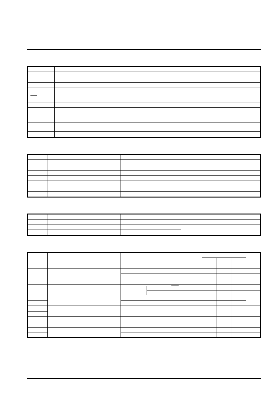
Bi-CMOS & DMOS 32BIT SERIAL-INPUT LATCHED DRIVER
M56694FP/GP
MITSUBISHI <CONTROL / DRIVER IC>
HVO1 – 32
Output driver (push-pull)
Function
Pin name
PIN FUNCTION DESCRIPTION
VDD
LGND
VH
PGND
CLK
SIN
SOUT
LAT
BLK
Serial data output
Latch input. When the LATCH is set to “H”, the data in the shift resister will enter the each latch circuit.
When the LATCH input is set to “L”, the data will be held.
Enable input for output control. When the BLK input is set to “L”, data in the latch circuit will appear at outputs.
When the BLK input is set to “H”, all outputs will be set to “L”.
Logic stage supply voltage
Logic stage ground
Output stage supply voltage
Output stage ground
Clock input for the internal shift resister. The data enter the internal shift resisters and the data in the shift registers will be
shifted in order by High to Low change of the clock.
Serial data input
Logic inputs voltage
Output voltage
Power dissipation range
Storage temperature range
Logic outputs voltage
Logic stage supply voltage
Output stage supply voltage
VI
VHVO
Tstg
-0.3 – 120
VO
-0.3 – VDD+0.3
VDD
-0.3 – 7
VH
Pd
-0.3 – VDD+0.3
-0.3 – VH
-55 – 150
940
High supply voltage output pin
Symbol
Ratings
Unit
Parameter
Conditions
ABSOLUTE MAXIMUM RATINGS (Ta=25
°C, unless otherwise noted)
V
°C
mW
Ta
≤ 25°C
Data output
0.4
V
3.1
High supply voltage output pin
V
-2
-100
SIN, LAT, CLK
BLK
VTH
VTL
Output protect operating voltage
IHVOH
“H” output current
VOH
VOL
Logic output voltage
VHVOH
Driver output voltage
VHVOL
IH
Supply current 2
Output all “H”, no load
Operating temperature
Supply voltage
Topr
10 – 110
VDD
4.5 – 5.5
VH
-20 – 75
Symbol
Ratings
Unit
Parameter
Conditions
RECOMMENDED OPERATING CONDITIONS
V
°C
Limits
Min.
Typ.
Max.
Symbol
Test conditions
Unit
Parameter
ELECTRICAL CHARACTERISTICS (VDD=5V, VH=110V and Ta=25
°C, unless otherwise noted)
IDD
IHVOL
Supply current 1
“L” input current
“L” output current
IOH = -0.1mA
100
4.5
1
0
2
0
-20
106
4.95
3.4
2
50
4
2
mA
V
IIH
IIL
“H” input current
No load
Output all “L”, no load
IHVOH = -0.5mA
IHVOL = 0.5mA
VIH=5V
Input pin
IOL = +0.1mA
High supply voltage output pin
VIL = 0V
02
A
0.7
0.04
-1
1
A
mA
A
-3
3
相關(guān)PDF資料 |
PDF描述 |
|---|---|
| M56710FP | F2F MAGNETIC STRIPE ENCORDING CARD READER |
| M56733 | 3-PHASE BRUSHLESS MOTOR CONTROL |
| M56733AFP | 3-PHASE BRUSHLESS MOTOR CONTROL |
| M56745FP | SPINDLE MOTOR DRIVER |
| M56748FP | 4-CHANNEL ACTUATOR MOTOR DRIVER |
相關(guān)代理商/技術(shù)參數(shù) |
參數(shù)描述 |
|---|---|
| M56694GP | 制造商:MITSUBISHI 制造商全稱:Mitsubishi Electric Semiconductor 功能描述:Bi-CMOS & DMOS 32BIT SERIAL-INPUT LATCHED DRIVER |
| M567 | 制造商:MA-COM 制造商全稱:M/A-COM Technology Solutions, Inc. 功能描述:CR-15 Package Handling and Mounting Procedure |
| M5670 SL001 | 制造商:Alpha Wire Company 功能描述:CBL 5PR 20AWG SLT 1000' |
| M5670 SL002 | 制造商:Alpha Wire Company 功能描述:CBL 5PR 20AWG SLT 500' |
| M5670 SL005 | 制造商:Alpha Wire Company 功能描述:CBL 5PR 20AWG SLT 100' |
發(fā)布緊急采購(gòu),3分鐘左右您將得到回復(fù)。