- 您現(xiàn)在的位置:買(mǎi)賣(mài)IC網(wǎng) > PDF目錄224146 > M40SZ100W (意法半導(dǎo)體) 5V or 3V NVRAM SUPERVISOR FOR LPSRAM PDF資料下載
參數(shù)資料
| 型號(hào): | M40SZ100W |
| 廠商: | 意法半導(dǎo)體 |
| 英文描述: | 5V or 3V NVRAM SUPERVISOR FOR LPSRAM |
| 中文描述: | 5V或3V的LPSRAM NVRAM中督導(dǎo)員 |
| 文件頁(yè)數(shù): | 3/19頁(yè) |
| 文件大?。?/td> | 285K |
| 代理商: | M40SZ100W |
第1頁(yè)第2頁(yè)當(dāng)前第3頁(yè)第4頁(yè)第5頁(yè)第6頁(yè)第7頁(yè)第8頁(yè)第9頁(yè)第10頁(yè)第11頁(yè)第12頁(yè)第13頁(yè)第14頁(yè)第15頁(yè)第16頁(yè)第17頁(yè)第18頁(yè)第19頁(yè)
11/19
M40SZ100Y, M40SZ100W
Power-on Reset Output
All microprocessors have a reset input which forc-
es them to a known state when starting. The
M40SZ100Y/W has a reset output (RST) pin which
page 7). This signal is an open drain configuration.
An appropriate pull-up resistor to VCC should be
chosen to control the rise time. This signal will be
valid for all voltage conditions, even when VCC
equals VSS (with valid battery voltage).
Once VCC exceeds the power failure detect volt-
age VPFD, an internal timer keeps RST low for
tREC to allow the power supply to stabilize.
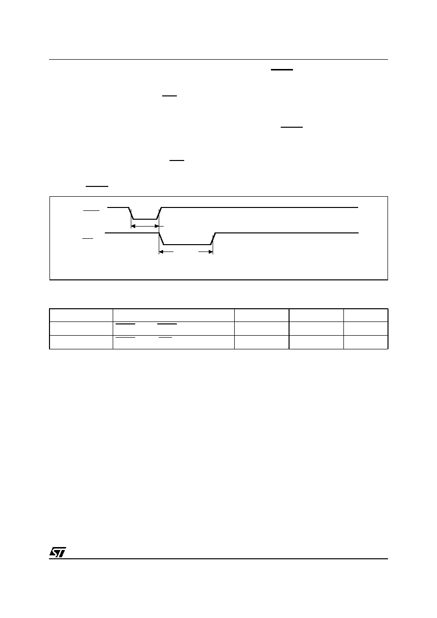
Reset Input (RSTIN)
The M40SZ100Y/W provides one independent in-
put which can generate an output reset. The dura-
tion and function of this reset is identical to a reset
illustrate the AC reset characteristics of this func-
tion. Pulses shorter than tRLRH will not generate a
reset condition. RSTIN is internally pulled up to
VCC through a 100k resistor.
Figure 12. RSTIN Timing Waveform
Note: With pull-up resistor
Table 7. Reset AC Characteristics
Note: 1. Valid for Ambient Operating Temperature: TA = –40 to 85°C; VCC = 2.7 to 3.6V or 4.5 to 5.5V (except where noted).
2. Pulse width less than 50ns will result in no RESET (for noise immunity).
Symbol
Parameter(1)
Min
Max
Unit
tRLRH
(2)
RSTIN Low to RSTIN High
200
ns
tR1HRH
(3)
RSTIN High to RST High
40
200
ms
AI04768
RST
(1)
RSTIN
tRLRH
tR1HRH
相關(guān)PDF資料 |
PDF描述 |
|---|---|
| M40SZ100WMH | 5V or 3V NVRAM SUPERVISOR FOR LPSRAM |
| M40SZ100WMQ | 5V or 3V NVRAM SUPERVISOR FOR LPSRAM |
| M40SZ100WSH | 5V or 3V NVRAM SUPERVISOR FOR LPSRAM |
| M40SZ100Y | 5V or 3V NVRAM SUPERVISOR FOR LPSRAM |
| M41ST84Y | 5.0 or 3.0V, 512 bit 64 x 8 SERIAL RTC with SUPERVISORY FUNCTIONS |
相關(guān)代理商/技術(shù)參數(shù) |
參數(shù)描述 |
|---|---|
| M40SZ100WMH | 制造商:STMICROELECTRONICS 制造商全稱(chēng):STMicroelectronics 功能描述:5V or 3V NVRAM SUPERVISOR FOR LPSRAM |
| M40SZ100WMH6 | 制造商:STMICROELECTRONICS 制造商全稱(chēng):STMicroelectronics 功能描述:5V or 3V NVRAM SUPERVISOR FOR LPSRAM |
| M40SZ100WMH6E | 制造商:STMICROELECTRONICS 制造商全稱(chēng):STMicroelectronics 功能描述:5 V or 3 V NVRAM supervisor for LPSRAM |
| M40SZ100WMH6F | 制造商:STMICROELECTRONICS 制造商全稱(chēng):STMicroelectronics 功能描述:5 V or 3 V NVRAM supervisor for LPSRAM |
| M40SZ100WMH6TR | 制造商:STMICROELECTRONICS 制造商全稱(chēng):STMicroelectronics 功能描述:5V or 3V NVRAM SUPERVISOR FOR LPSRAM |
發(fā)布緊急采購(gòu),3分鐘左右您將得到回復(fù)。