- 您現(xiàn)在的位置:買賣IC網(wǎng) > PDF目錄385509 > M3819 (Mitsubishi Electric Corporation) 8-Bit Single Chip Microcomputer(8位單片微控制器) PDF資料下載
參數(shù)資料
| 型號(hào): | M3819 |
| 廠商: | Mitsubishi Electric Corporation |
| 英文描述: | 8-Bit Single Chip Microcomputer(8位單片微控制器) |
| 中文描述: | 8位單片機(jī)(8位單片微控制器) |
| 文件頁數(shù): | 176/217頁 |
| 文件大小: | 2564K |
| 代理商: | M3819 |
第1頁第2頁第3頁第4頁第5頁第6頁第7頁第8頁第9頁第10頁第11頁第12頁第13頁第14頁第15頁第16頁第17頁第18頁第19頁第20頁第21頁第22頁第23頁第24頁第25頁第26頁第27頁第28頁第29頁第30頁第31頁第32頁第33頁第34頁第35頁第36頁第37頁第38頁第39頁第40頁第41頁第42頁第43頁第44頁第45頁第46頁第47頁第48頁第49頁第50頁第51頁第52頁第53頁第54頁第55頁第56頁第57頁第58頁第59頁第60頁第61頁第62頁第63頁第64頁第65頁第66頁第67頁第68頁第69頁第70頁第71頁第72頁第73頁第74頁第75頁第76頁第77頁第78頁第79頁第80頁第81頁第82頁第83頁第84頁第85頁第86頁第87頁第88頁第89頁第90頁第91頁第92頁第93頁第94頁第95頁第96頁第97頁第98頁第99頁第100頁第101頁第102頁第103頁第104頁第105頁第106頁第107頁第108頁第109頁第110頁第111頁第112頁第113頁第114頁第115頁第116頁第117頁第118頁第119頁第120頁第121頁第122頁第123頁第124頁第125頁第126頁第127頁第128頁第129頁第130頁第131頁第132頁第133頁第134頁第135頁第136頁第137頁第138頁第139頁第140頁第141頁第142頁第143頁第144頁第145頁第146頁第147頁第148頁第149頁第150頁第151頁第152頁第153頁第154頁第155頁第156頁第157頁第158頁第159頁第160頁第161頁第162頁第163頁第164頁第165頁第166頁第167頁第168頁第169頁第170頁第171頁第172頁第173頁第174頁第175頁當(dāng)前第176頁第177頁第178頁第179頁第180頁第181頁第182頁第183頁第184頁第185頁第186頁第187頁第188頁第189頁第190頁第191頁第192頁第193頁第194頁第195頁第196頁第197頁第198頁第199頁第200頁第201頁第202頁第203頁第204頁第205頁第206頁第207頁第208頁第209頁第210頁第211頁第212頁第213頁第214頁第215頁第216頁第217頁
163
2. APPLICAT ION
MITSUBISHI MICROCOMPUTER
3819 Group
2.9 Clock generating circuit
3819 Group USER’S MANUAL
Power failure detection signal
Input port
(
Note
)
3819 group
Signal is detected by inputting
to each input port, interrupt
input pin, and analog input pin.
Note :
X
IN
X
CIN
Internal system
clock
f(X
IN
)/2
f(X
CIN
)/2
Change the internal
system clock to f(X
IN
)/2
(high-speed mode).
f(X
IN
)/8
Release reset
Detection of power failure
Selection of X
CIN
oscillating function
After detecting a power
failure, change the internal
system clock to f(X
CIN
) and
stop operating of f(X
IN
).
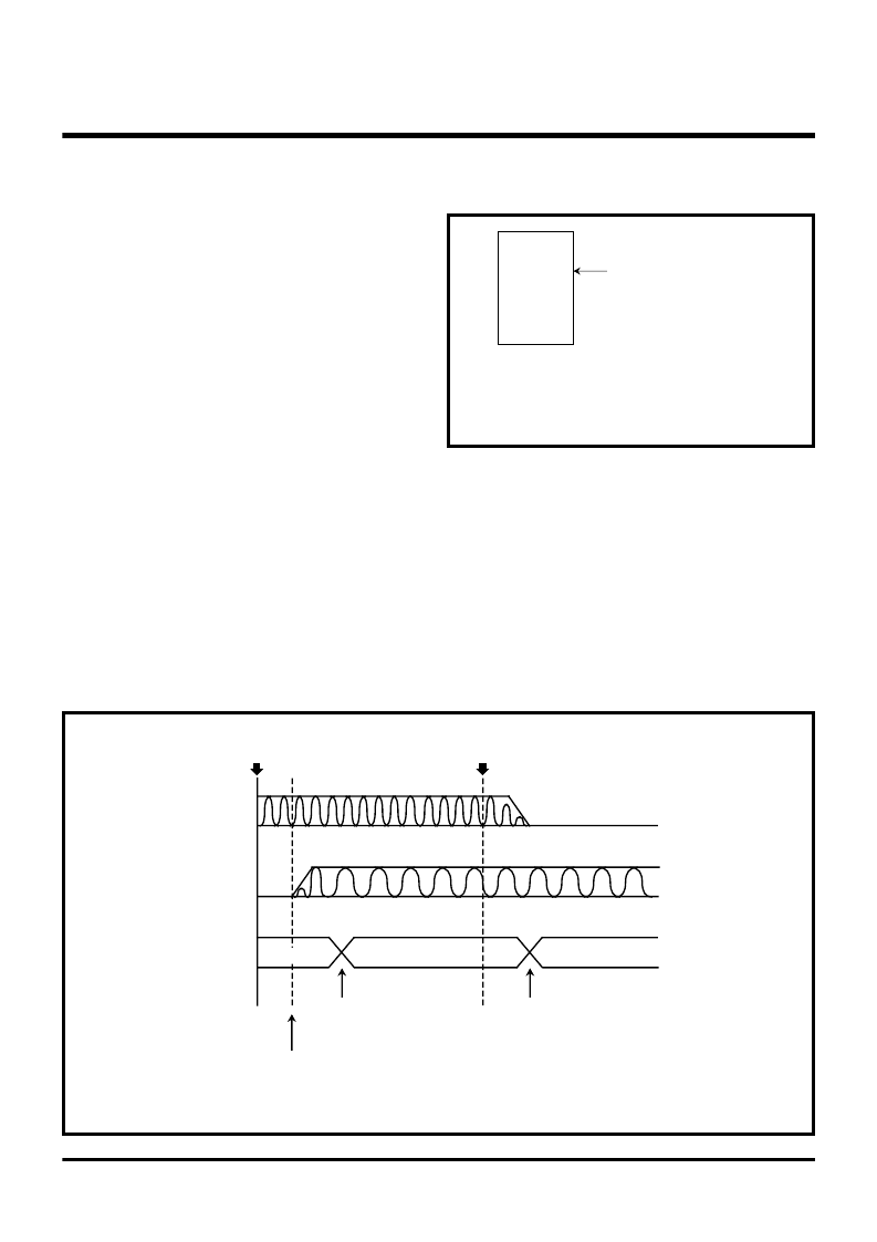
(2) Counting without clock error during a power
failure
Outline :
It keeps counting without clock errors
during a power failure.
Specifications :
Keep a power consumption as low as possible
while maintaining a clock function.
Keep counting a clock correctly.
f(X
IN
) = 4.19 MHz, f(X
CIN
) = 32.768 kHz
The Timer 1 interrupt is used in a normal power state.
The Timer 3 interrupt is used during a power failure.
Port processing
Input port : Fix to “H” or “L” level in the external
unit.
Output port : Fix to an output level which does not
cause a current flow to the external
unit.
[
Example
]
When a circuit turns on LED at “L” output level, fix the output level to “H”.
I/O port : Input port — Fix to “H” or “L” level in the external unit.
Output port — Output the data which does not consume current.
V
REF
: Supplying to the Reference voltage input pin is stopped by the external circuit.
P4
5
/ZCR (using as the input port) : Fix to “H” level in the external unit.
Figure 2.9.15 shows a timing chart of counting without clock errors during a power failure, Figure 2.9.16 shows a
structure of a clock counter, and Figures 2.9.17 and 2.9.18 show a setting of related registers.
Fig. 2.9.15 Timing chart of counting without clock errors during a power failure
Fig. 2.9.14 Connection diagram
[Counting without
clock errors during a power failure]
相關(guān)PDF資料 |
PDF描述 |
|---|---|
| M381L5623MTM-CA2 | DDR SDRAM Unbuffered Module |
| M381L5623MTM-CB0 | DDR SDRAM Unbuffered Module |
| M381L5623MTM-CB3 | DDR SDRAM Unbuffered Module |
| M381L5623MTN | DDR SDRAM Unbuffered Module |
| M38207M8-051 | 1 watt dc-dc converters |
相關(guān)代理商/技術(shù)參數(shù) |
參數(shù)描述 |
|---|---|
| M38197MA127F | 制造商:Panasonic Industrial Company 功能描述:IC |
| M38197MA131F | 制造商:Panasonic Industrial Company 功能描述:IC |
| M38197MA137F | 制造商:Panasonic Industrial Company 功能描述:IC |
| M38197MA161F | 制造商:Panasonic Industrial Company 功能描述:IC |
| M38197MA181F | 制造商:Panasonic Industrial Company 功能描述:IC |
發(fā)布緊急采購,3分鐘左右您將得到回復(fù)。