- 您現(xiàn)在的位置:買賣IC網(wǎng) > PDF目錄370849 > M37736EHBXXXGP (Mitsubishi Electric Corporation) PROM VERSION OF M37736MHBXXXGP(MICROCOMPUTERS) PDF資料下載
參數(shù)資料
| 型號(hào): | M37736EHBXXXGP |
| 廠商: | Mitsubishi Electric Corporation |
| 英文描述: | PROM VERSION OF M37736MHBXXXGP(MICROCOMPUTERS) |
| 中文描述: | PROM的版本M37736MHBXXXGP(微型) |
| 文件頁數(shù): | 13/96頁 |
| 文件大小: | 1328K |
| 代理商: | M37736EHBXXXGP |
第1頁第2頁第3頁第4頁第5頁第6頁第7頁第8頁第9頁第10頁第11頁第12頁當(dāng)前第13頁第14頁第15頁第16頁第17頁第18頁第19頁第20頁第21頁第22頁第23頁第24頁第25頁第26頁第27頁第28頁第29頁第30頁第31頁第32頁第33頁第34頁第35頁第36頁第37頁第38頁第39頁第40頁第41頁第42頁第43頁第44頁第45頁第46頁第47頁第48頁第49頁第50頁第51頁第52頁第53頁第54頁第55頁第56頁第57頁第58頁第59頁第60頁第61頁第62頁第63頁第64頁第65頁第66頁第67頁第68頁第69頁第70頁第71頁第72頁第73頁第74頁第75頁第76頁第77頁第78頁第79頁第80頁第81頁第82頁第83頁第84頁第85頁第86頁第87頁第88頁第89頁第90頁第91頁第92頁第93頁第94頁第95頁第96頁
13
PRELIMINARY
Notice: This is not a final specification.
Some parametric limits are subject to change.
MITSUBISHI MICROCOMPUTERS
M37736MHBXXXGP
SINGLE-CHIP 16-BIT CMOS MICROCOMPUTER
Interrupt control registers
A-D/UART2 trans./rece. interrput control register
UART0 transmit interrput control register
UART0 receive interrput control register
UART1 transmit interrput control register
UART1 receive interrupt control register
Timer A0 interrupt control register
Timer A1 interrupt control register
Timer A2 interrupt control register
Timer A3 interrupt control register
Timer A4 interrupt control register
Timer B0 interrupt control register
Timer B1 interrupt control register
0
interrupt control register
1
interrupt control register
INT
2
/Key input interrupt control register
addresses
000070
16
000071
16
000072
16
000073
16
000074
16
000075
16
000076
16
000077
16
000078
16
000079
16
00007A
16
00007B
16
00007C
16
00007D
16
00007E
16
00007F
16
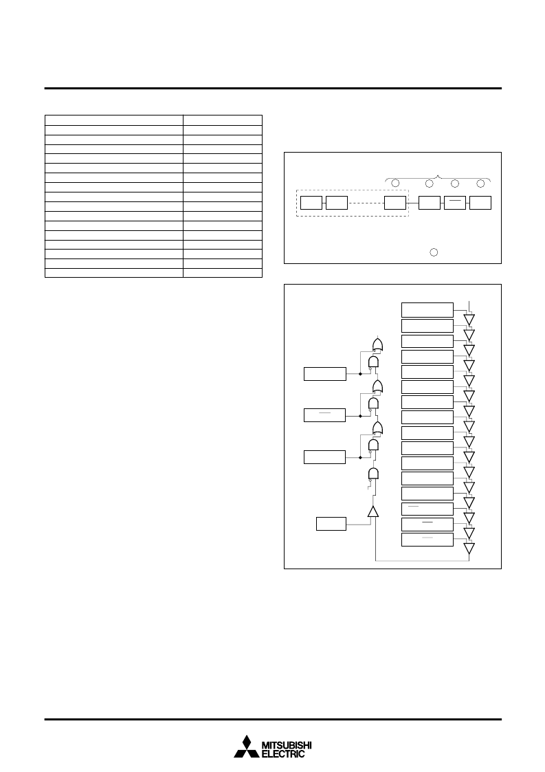
Table 2. Addresses of interrupt control registers
Interrupts caused by a BRK instruction and when dividing by zero
are software interrupts and are not included in this list.
Other interrupts previously mentioned are A-D converter, UART,
Timer, INT interrupts. The priority of these interrupts can be changed
by changing the interrupt priority level selection bits of the
corresponding interrupt control register with software.
Figure 8 shows a diagram of the interrupt priority detection circuit.
When an interrupt is caused, the each interrupt device compares its
own priority with the priority from above and if its own priority is higher,
then it sends the priority below and requests the interrupt. If the
priorities are the same, the one above has priority.
This comparison is repeated to select the interrupt with the highest
priority among the interrupts that are being requested. Finally the
selected interrupt is compared with the processor interrupt priority
level (IPL) contained in the processor status register (PS), and the
request is accepted if it is higher than IPL and the interrupt disable
___
DBC
, and watchdog timer interrupts are not affected by the interrupt
disable flag (I).
When an interrupt is accepted, the contents of the processor status
register (PS) is saved to the stack and the interrupt disable flag (I) is
set to “1”.
Furthermore, the interrupt request bit of the accepted interrupt is
cleared to “0” and the processor interrupt priority level (IPL) in the
processor status register (PS) is replaced by the priority level of the
accepted interrupt.
Therefore, multiple interrupts are possible by resetting the interrupt
disable flag (I) to “0” and enable further interrupts.
For reset,
DBC
, watchdog timer, zero divide, and BRK instruction
interrupts, which do not have an interrupt control register, the
processor interrupt level (IPL) is set as shown in Table 3.
Priority detection is performed by latching the interrupt request bit
and interrupt priority level selection bits so that they do not change.
They are sampled at the first half and latched at the last half of the
operation code fetch cycle.
Because priority detection takes some time, no sampling pulse is
generated for a certain interval even if it is the next operation code
fetch cycle.
Fig. 8 Interrupt priority detection circuit
Fig. 7 Interrupt priority
Priority is determined by hardware
3
4
Watchdog
timer
DBC
Reset
A-D converter, UART, Timer, INT interrupts
Priority can be changed by software inside
1
2
4
Wtimer
A-D/UART2
trans./rece.
Level 0
INT
0
UART1 transmit
UART1 receive
UART0 transmit
UART0 receive
Timer B2
Timer B1
Timer B0
Timer A4
Timer A3
Timer A2
Timer A1
Timer A0
INT
2
/Key input
INT
1
IPL
Interrupt disable flag(I)
DBC
Reset
Interrupt request
相關(guān)PDF資料 |
PDF描述 |
|---|---|
| M37736MHBXXXGP | SINGLE-CHIP 16-BIT CMOS MICROCOMPUTER |
| M37753FFCFP | SINGLE CHIP 16 BIT CMOS MICROCOMPUTER FLASH MEMORY VERSION |
| M37753FFCHP | SINGLE CHIP 16 BIT CMOS MICROCOMPUTER FLASH MEMORY VERSION |
| M37754M8C-XXXGP | SINGLE-CHIP 16BIT CMOS MICROCOMPUTER |
| M37754M8C-XXXHP | SINGLE-CHIP 16BIT CMOS MICROCOMPUTER |
相關(guān)代理商/技術(shù)參數(shù) |
參數(shù)描述 |
|---|---|
| M37736EHL | 制造商:MITSUBISHI 制造商全稱:Mitsubishi Electric Semiconductor 功能描述:PROM VERSION OF M37736MHLXXXHP(MICROCOMPUTERS) |
| M37736EHLXXXHP | 制造商:RENESAS 制造商全稱:Renesas Technology Corp 功能描述:PROM VERSION OF M37736MHLXXXHP |
| M37736M4B | 制造商:MITSUBISHI 制造商全稱:Mitsubishi Electric Semiconductor 功能描述:SINGLE-CHIP 16-BIT CMOS MICROCOMPUTER |
| M37736M4BXXXGP | 制造商:MITSUBISHI 制造商全稱:Mitsubishi Electric Semiconductor 功能描述:SINGLE-CHIP 16-BIT CMOS MICROCOMPUTER |
| M37736M4L | 制造商:MITSUBISHI 制造商全稱:Mitsubishi Electric Semiconductor 功能描述:SINGLE-CHIP 16-BIT CMOS MICROCOMPUTER |
發(fā)布緊急采購(gòu),3分鐘左右您將得到回復(fù)。