- 您現(xiàn)在的位置:買賣IC網(wǎng) > PDF目錄30743 > LM1253AAE/NA (NATIONAL SEMICONDUCTOR CORP) ON-SCREEN DISPLAY IC, PDIP28 PDF資料下載
參數(shù)資料
| 型號(hào): | LM1253AAE/NA |
| 廠商: | NATIONAL SEMICONDUCTOR CORP |
| 元件分類: | 畫(huà)面疊加 |
| 英文描述: | ON-SCREEN DISPLAY IC, PDIP28 |
| 封裝: | 0.600 INCH, PLASTIC, DIP-28 |
| 文件頁(yè)數(shù): | 20/61頁(yè) |
| 文件大?。?/td> | 1671K |
| 代理商: | LM1253AAE/NA |
第1頁(yè)第2頁(yè)第3頁(yè)第4頁(yè)第5頁(yè)第6頁(yè)第7頁(yè)第8頁(yè)第9頁(yè)第10頁(yè)第11頁(yè)第12頁(yè)第13頁(yè)第14頁(yè)第15頁(yè)第16頁(yè)第17頁(yè)第18頁(yè)第19頁(yè)當(dāng)前第20頁(yè)第21頁(yè)第22頁(yè)第23頁(yè)第24頁(yè)第25頁(yè)第26頁(yè)第27頁(yè)第28頁(yè)第29頁(yè)第30頁(yè)第31頁(yè)第32頁(yè)第33頁(yè)第34頁(yè)第35頁(yè)第36頁(yè)第37頁(yè)第38頁(yè)第39頁(yè)第40頁(yè)第41頁(yè)第42頁(yè)第43頁(yè)第44頁(yè)第45頁(yè)第46頁(yè)第47頁(yè)第48頁(yè)第49頁(yè)第50頁(yè)第51頁(yè)第52頁(yè)第53頁(yè)第54頁(yè)第55頁(yè)第56頁(yè)第57頁(yè)第58頁(yè)第59頁(yè)第60頁(yè)第61頁(yè)
Micro-Controller Interface
The micro-controller interfaces to the LM1253A pre-amp via
an I
2C interface. The protocol of the interface begins with a
Start Pulse followed by a byte comprised of a seven bit Slave
Device Address and a Read/Write bit. Since the first byte is
composed of both the address and the read/write bit the
address of the LM1253A for writing is BAh (1011 1010) and
the address for reading is BBh (1011 1011). The develop-
ment software provided by National Semiconductor will au-
tomatically take care of the difference between the read and
write addresses if the target address under the communica-
tions tab is set to BAh.
Figures 39, 40 show a write and read
sequence across the I
2C interface.
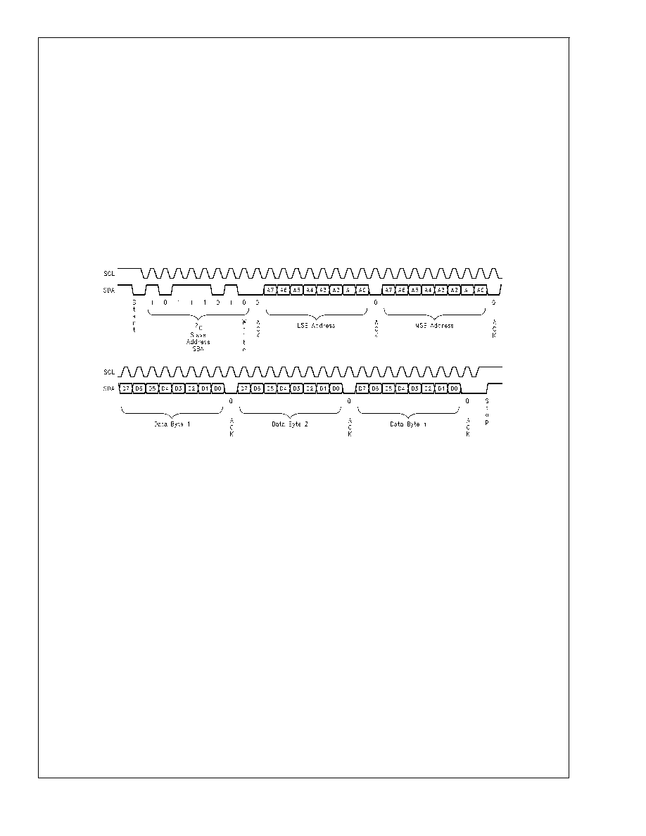
Write Sequence
The write sequence begins with a start condition which
consists of the master pulling SDA low while SCL is held
high. The slave device address is next sent. The address
byte is made up of an address of seven bits (7-1) and the
read/write bit (0). Bit 0 is low to indicate a write operation.
Each byte that is sent is followed by an acknowledge. When
SCL is high the master will release the SDA line. The slave
must pull SDA low to acknowledge. The register to be written
to is next sent in two bytes, the least significant byte being
sent first. The master can then send the data, which consists
of one or more bytes. Each data byte is followed by an
acknowledge bit. If more than one data byte is sent the data
will increment to the next address location. See
Figure 39.
Read Sequence
Read sequences are comprised of two I
2C transfer se-
quences: The first is a write sequence that only transfers the
two byte address to be accessed. The second is a read
sequence that starts at the address transferred in the previ-
ous address only write access and increments to the next
address upon every data byte read. This is shown in
Figure
40.
DS101265-45
FIGURE 39. I
2C Write Sequence
LM1253A
www.national.com
27
相關(guān)PDF資料 |
PDF描述 |
|---|---|
| LM1267NA/NOPB | 3 CHANNEL, VIDEO PREAMPLIFIER, PDIP24 |
| LM1269NA/NOPB | 3 CHANNEL, VIDEO PREAMPLIFIER, PDIP24 |
| LM1276AAA/NA | 1 CHANNEL, VIDEO PREAMPLIFIER, PDIP28 |
| LM1279AN/NOPB | 3 CHANNEL, VIDEO AMPLIFIER, PDIP20 |
| LM1279N/NOPB | 1 CHANNEL, VIDEO AMPLIFIER, PDIP20 |
相關(guān)代理商/技術(shù)參數(shù) |
參數(shù)描述 |
|---|---|
| LM1253AN | 制造商:NSC 制造商全稱:National Semiconductor 功能描述:Monolithic Triple 180 MHz I2C CRT Pre-amp With Integrated Analog On Screen Display (OSD) Generator |
| LM-1256 | 制造商:ROHM 制造商全稱:Rohm 功能描述:16 x 16 matrix displays |
| LM-1256_1 | 制造商:ROHM 制造商全稱:Rohm 功能描述:16】16 matrix displays |
| LM-1256LB1 | 制造商:ROHM 制造商全稱:Rohm 功能描述:16】16 matrix displays |
| LM125AN | 制造商:NSC 制造商全稱:National Semiconductor 功能描述:VOLTAGE REGULATORS |
發(fā)布緊急采購(gòu),3分鐘左右您將得到回復(fù)。